


P 6/ 20
Repair
[3] DISASSEMBLY/ASSEMBLY
[3]-2. Barrel section (cont.)
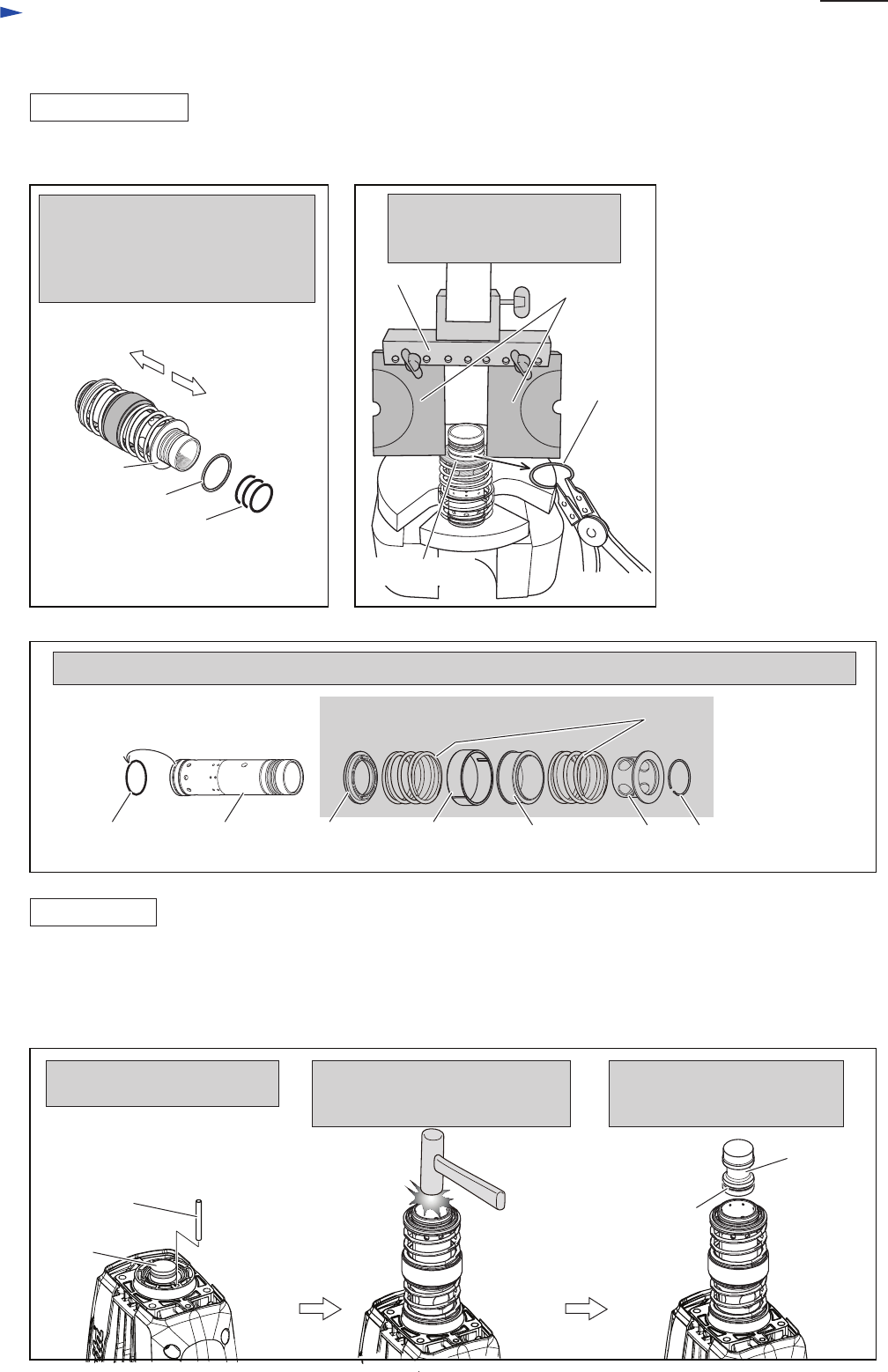
DISASSEMBLING
ASSEMBLING
Crank housing side
Ring 45
O ring 36 (3pcs.)
Slide sleeve
Compression spring 58
Tool holder side
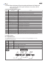
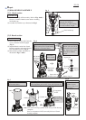
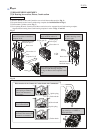
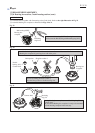
Remove O ring 36 and Ring 45 from
Crank housing side of Cylinder 40 as
illustrated below.
Ring spring 43 still remains on the
Cylinder as a stopper for Slide sleeve.
1R024
or
1R356
Fig. 9 Fig. 10
Fig. 11
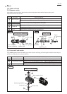
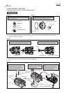
O Ring 41
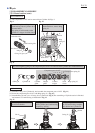
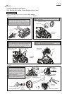
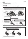
After removing Ring spring 43, the component parts of AVT are removed from Cylinder 40 as illustrated below.
Cylinder 40 Cylinder
guide
Weight
guide
Counter
weight
1R306
Pressing down Slide sleeve as
illustrated below, remove Ring
spring 43.
Ring
spring 43
Slide
sleeve
Ring spring 43
Component parts of AVT
Slide sleeve
(4) The components of AVT can be removed from Cylinder 40 (Figs. 9
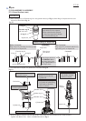
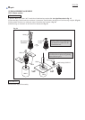
(1) Assemble O ring 41 to Cylinder 40. And assemble the component parts of AVT. (Fig. 11)
(2) Secure the component parts of AVT with Ring spring 43. (Fig. 10)
(3) Assemble Ring 45 and 3 pcs. of O ring 36 to Cylinder 40. (Fig. 9) The assembling of Cylinder section is finished.
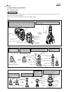
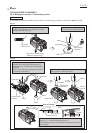
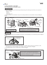
And mount it to Crank housing as illustrated in Fig. 12.
Pin 6
Piston
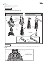
Do not forget to assemble Pin 6
for AVT mechanism.
Aligning Cylinder hole to Piston,
insert Cylinder into Crank housing
complete by striking.
O ring 31.5
Facing O Ring 31.5 assembled
side to Crank housing complete,
insert Striker into Cylinder 40.
Striker
Fig. 12