


P 16/ 20
Repair
[3] DISASSEMBLY/ASSEMBLY
[3]-6. Electrical parts in Handle section
DISASSEMBLING
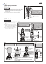
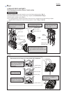
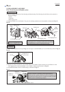
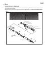
(1) Remove Handle section from Crank housing and Motor housing. The following electrical Parts can be replaced as
illustrated in Fig. 2.
* Switch
* Controller
* Power supply cord
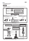
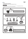
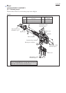
(2) Separate Handle cover from Handle. The parts for switching mechanism are disassembled as illustrated in Fig. 35.
ASSEMBLING
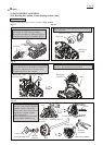
Disassemble Switch lever from Side lever by unscrewing
4x18 Tapping screw. And Remove Slide lever from Handle.
Pay attention not to lose Leaf spring in this step.
Switch lever
Switch
lever
Slide lever
Unscrew 4x18 Tapping screw,
and remove Handle cover.
Leaf
spring
Handle cover
Handle
4x18 Tapping screw
4x18 Tapping screw
4x18 Tapping screw
Fig. 35
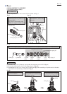
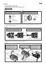
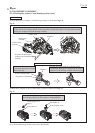
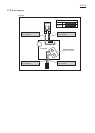
(1) When replacing Switch in the step of Fig. 2, do not forget to assemble Rubber pin 4 to the illustrated position in Fig. 36.
Switch
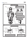
Tumbler of Switch is controlled by the pronged portion of
Switch lever that is joined to Slide lever with 4x18 Tapping screw.
Fitting the Prong of Switch lever to Tumbler of Switch, assemble
Handle section to Crank housing complete.
Rubber Pin 4
(green color)
Fig. 36
Fig. 37
Tumbler of
Switch
Prong of
Switch Lever
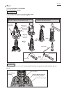
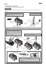
(2) Mount Leaf spring to Slide lever, and assemble Slide lever to Handle. Fasten Switch lever to the Slide lever with
4x18 Tapping screw. And mount Handle cover to Handle. Refer to the illustrations in Fig. 35.
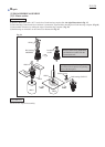
(3) Assemble the Handle section to Crank housing as illustrated in Fig. 37.
Handle section
Slide Lever