


OM-129 647 Page 14
SECTION 4 − INSTALLATION
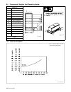
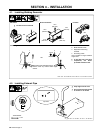
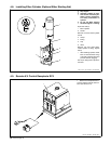
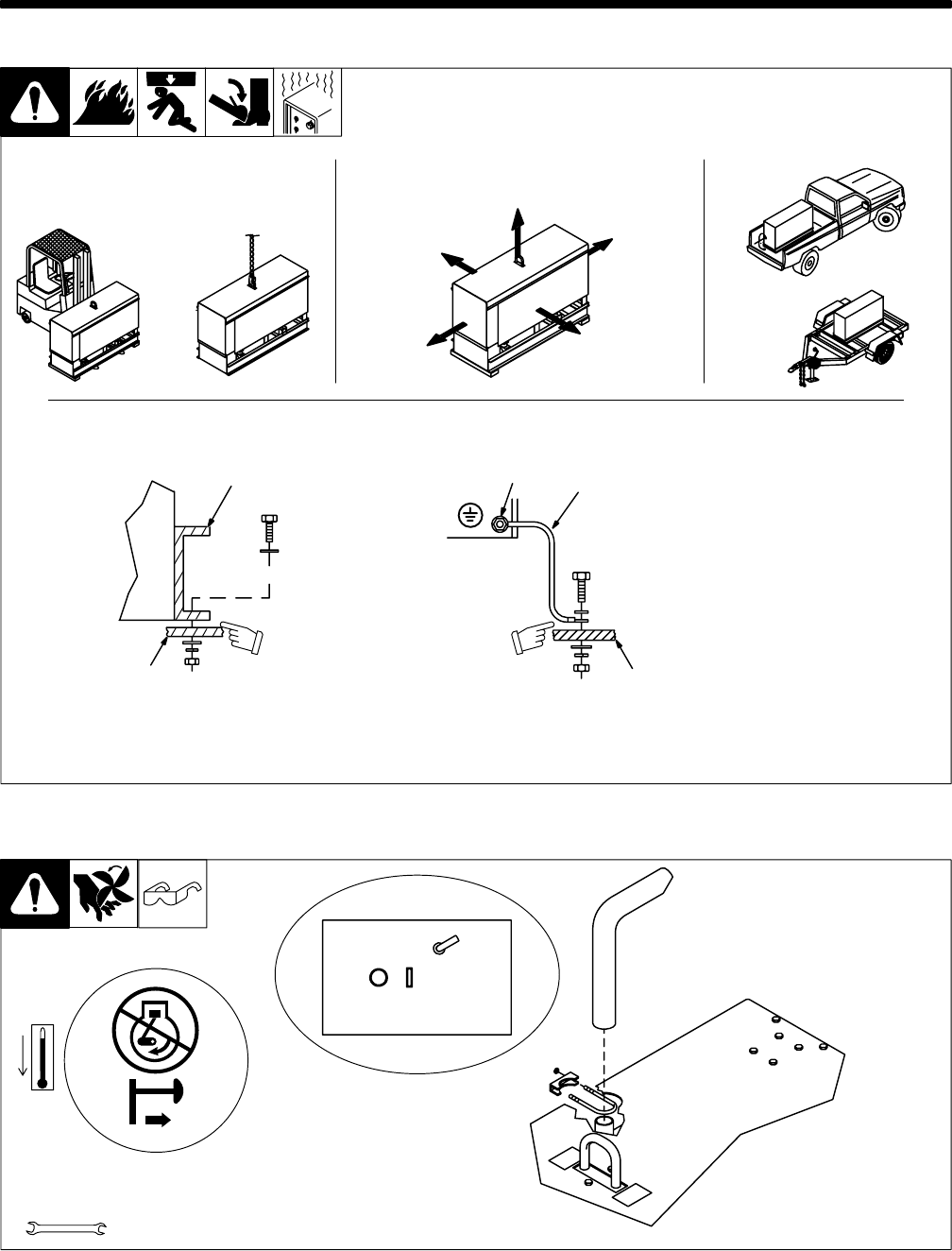
4-1. Installing Welding Generator
install1 3/96 − Ref. ST-800 652 / Ref. ST-800 477-A / ST-158 936-A / S-0854
1
2
Electrically bond generator frame to
vehicle frame by metal-to-metal
contact.
GND/PE
3
4
1 Generator Base
2 Metal Vehicle Frame
3 Equipment Grounding
Terminal
4 Grounding Cable
Use #10 AWG or larger insulated
copper wire.
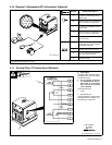
Y If unit does not have GFCI
receptacles, use GFCI-
protected extension cord.
2
OR
18 in
(460 mm)
18 in
(460 mm)
18 in
(460 mm)
18 in
(460 mm)
18 in
(460 mm)
OR
Movement Airflow Clearance Location
Grounding
OR
Y Do Not Lift Unit From End
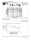
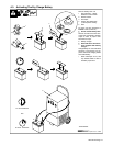
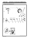
4-2. Installing Exhaust Pipe
Y Stop engine and let cool.
1/2 in
Tools Needed:
exh_pipe2 4/96 − ST-154 089-A / ST-154 611 / ST-180 933-B
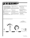
Y Do not blow exhaust toward
air cleaner or air intake.
Top View