


OM-129 647 Page 23
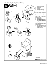
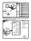
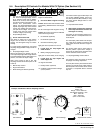
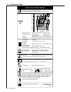
5-4. Description Of Controls For Models With CV Option (See Section 5-3)
. This unit has a max OCV control circuit
that resets Amperage/Voltage Control
R1 to maximum when the arc breaks.
When an arc is struck, weld output con-
trol returns to the R1 front panel or com-
bination front panel/remote control
setting. The Amperage/Voltage control
adjusts amperage only when constant
current (CC) welding and does not ad-
just open-circuit voltage. The max OCV
control circuit does not function when
constant voltage (CV) welding.
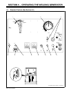
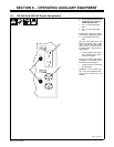
1 Ampere Range Switch
Y Do not switch under load.
Use switch to select one of five ampere
ranges. Use the lower four ranges for CC
welding. Use the highest range for CV/DC
welding.
For most welding applications, use lowest
amperage range possible to help prevent arc
outages.
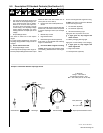
2 Amperage/Voltage Control
With CC/CV switch in CC position, use con-
trol to adjust amperage within range selected
by Ampere Ranges switch. With switch in CV
position, use control to adjust voltage.
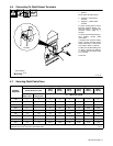
Weld output would be 223 A DC with
amperage controls set as shown (50% of 125
to 320 A).
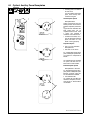
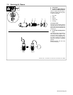
3 Manual Stop Control
4 Engine Start Button
5 Ether Starting Aid Switch (Optional)
Push switch up and release while cranking
engine to release ether.
Y Do not use Ether if engine is running.
To Start: Press button and use Ether switch
(if necessary). Release button when engine
starts.
Do not crank engine while engine is turning.
To Stop: Pull control out and hold. Release
control when engine stops.
6 DC Ammeter (Optional)
7 DC Voltmeter (Optional)
8 Oil Pressure Warning Light
Light goes off if oil pressure is too low.
Y If light goes off, stop engine and
check oil level.
9 Battery Charging Warning Light
Light goes on when battery is not charging.
Y If light goes on, stop engine and
check engine belt.
10 Engine Hour Meter
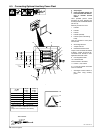
11 Polarity Switch (Optional)
12 Constant Current/Constant Voltage
(CC/CV) Switch
Use switch to select type of weld output. Use
CC for Stick (SMAW) welding. Use CV for
wire feed processes (MIG, FCAW). If using
CV, place Ampere Range switch in maxi-
mum position.
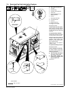
13 Output/Contactor Switch
Y Weld output terminals are energized
when Output/Contactor switch is On
and engine is running
Use switch to control remote contactor con-
nected to Remote 14 receptacle RC3 or ter-
minal strip 2T.
For weld output, place switch in the On posi-
tion. Open-circuit voltage is present at the
weld output terminals whenever engine is
running.
For remote output control, place switch in
Remote position. Open-circuit voltage is
present at the weld output terminals when
remote contactor switch is closed.
14 Amperage/Voltage Control Switch
Use switch to select front panel or remote
amperage and voltage adjustment.
For front panel control, place switch in Panel
position. For remote control, place switch in
Remote position and connect remote control
to Remote 14 receptacle RC3 or terminal
strip 2T.
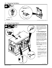
S-185 440 / Ref. ST-185 762-B / S-0774
Min
Max
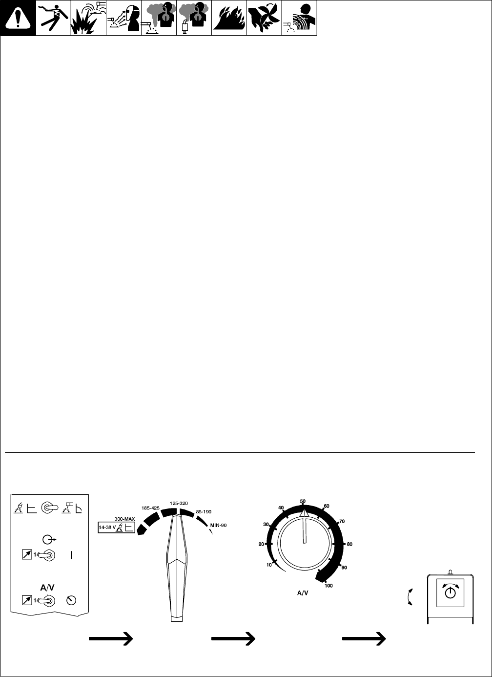
Set Switches Adjust Remote ControlSet Range Set Percentage
Example: Combination Remote Amperage Control
In Example:
Mode = CC
Range = 125 to 320 A DC
Percentage Of Range = 50%
Min = 125 A DC
Max = 223 A DC
(50% of 125 to 320)
(223 A DC)
(125 A DC)