


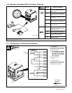
OM-129 647 Page 21
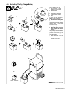
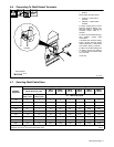
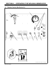
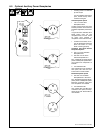
5-2. Description Of Standard Controls (See Section 5-1)
. This unit has a max OCV control circuit
that resets the Amperage/Voltage Con-
trol to maximum when the arc breaks.
When an arc is struck, weld output con-
trol returns to the front panel or remote
control setting. The Amperage/voltage
Control adjusts amperage only when
welding and does not adjust open-circuit
voltage.
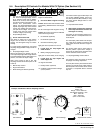
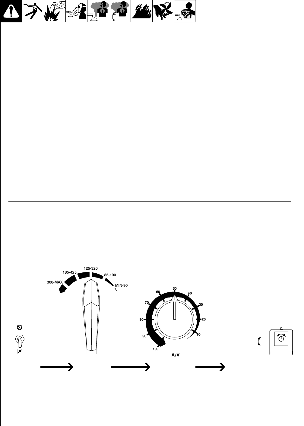
1 Ampere Range Switch
Use switch to select one of five ampere
ranges.
For most welding applications, use lowest
amperage range possible to help prevent arc
outages.
Y Do not switch under load.
2 Amperage/Voltage Control
Control adjusts amperage within range se-
lected by Ampere Range switch. Weld output
would be 223 A DC with controls set as
shown (50% of 125 to 320 A).
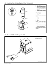
3 Remote A/V Control Receptacle And
Switch
Connect optional remote control to RC3 (See
Section 4-9). Use switch to select front panel
or remote amperage control (see example
below).
4 Manual Stop Control
5 Engine Start Button
6 Ether Starting Aid Switch (Optional)
Push switch up and release while cranking
engine to release ether.
Y Do not use Ether if engine is running.
To Start: Press button and use Ether switch
(if necessary). Release button when engine
starts.
Do not crank engine while engine is turning.
To Stop: Pull control out and hold. Release
control when engine stops.
7 DC Ammeter (Optional)
8 DC Voltmeter (Optional)
9 Oil Pressure Warning Light
Light goes off if oil pressure is too low.
Y If light goes off, stop engine and
check oil level.
10 Battery Charging Warning Light
Light goes on when battery is not charging.
Y If light goes on, stop engine and
check engine belt.
11 Engine Hour Meter
12 Polarity Switch (Optional)
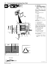
S-0774 / Ref. ST-180 933-B
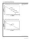
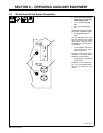
Example: Combination Remote Amperage Control
In Example:
Range = 125 to 320 A
Percentage Of Range = 50%
Max = 223 A DC (50% of 125 to 320)
Adjust Optional Remote ControlSet Switches Set Range Set Percentage
Max (223 A DC)
Min (100 A DC)