


OM-129 647 Page 19
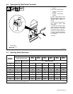
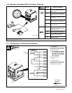
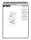
4-10. Remote 14 Receptacle RC3 Information (Optional)
Socket* Socket Information
AJ
B
K
I
A 24 volts ac. Protected by circuit
breaker CB4.
B
I
C
L
NH
D
M
G
B Contact closure to A completes 24
volts ac contactor control circuit.
D
M
G
E
F
I 115 volts ac. Protected by circuit
breaker CB3.
J Contact closure to I completes 115
volts ac contactor control circuit.
OR
G Circuit common for 24 and 115
volts ac circuits.
OR
C 0 to +10 volts dc output to remote
control from min to max of Amper-
age/Voltage control R1.
A/V
D Remote control circuit common.
Ref. ST-800 862-B
A/V
E 0 to +10 volts dc input command
signal from remote control.
Ref
.
ST 800 862 B
K Chassis common.
*The remaining sockets are not used.
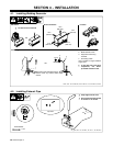
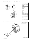
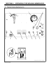
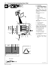
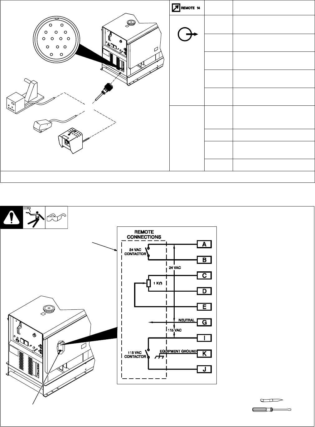
4-11. Terminal Strip 2T Connections (Optional)
Ref. ST-800 862-B / Ref. ST-185 316
Y Stop engine.
If remote control plug does not fit in
receptacle RC3, wire cord directly
to terminal strip 2T.
Y Do not connect to Remote
14 receptacle RC3 and ter-
minal strip 2T at the same
time. Use only one remote
control method.
Open right side door.
1 Cover
2 Terminal Strip 2T
Connect leads to 2T using terminal
information shown in Section 4-10.
Reinstall cover. Close door.
Tools Needed:
1
2