


OM-129 647 Page 35
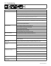
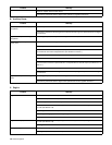
7-11. Troubleshooting
A. Welding
Trouble Remedy
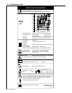
No weld output. Check position of Ampere Range switch.
Check position of optional polarity switch.
Disconnect equipment from auxiliary power receptacles during start-up.
Place A/V Control switch in Panel position, or place switch in Remote position and connect remote con-
trol to Remote A/V Control receptacle RC3 (see Sections 4-9 and 5-1).
Check and secure connections to Remote A/V Control receptacle RC3 (see Section 4-9).
Place optional Output/Contactor Control switch in On position, or place switch in Remote position and
connect remote contactor to optional Remote 14 receptacle RC3 or terminal strip 2T (see Sections 4-10
and 4-11).
Have Factory Authorized Service Agent check brushes and slip rings, field excitation circuit, and
optional field current regulator board PC1.
Erratic weld output. Check and tighten connections inside and outside unit.
Be sure connection to work piece is clean and tight.
Use dry, properly stored electrodes.
Remove excessive coils from weld cables.
Check Ampere Range switch connections and contacts.
High or low weld output. Check engine speed, and adjust if necessary (see Section 7-5).
Check optional CC/CV switch position.
Low open-circuit voltage. Check engine speed, and adjust if necessary (see Section 7-5).
Check optional CC/CV switch position.
Have Factory Authorized Service Agent check optional field current regulator board PC1 and CV
regulator board PC2.
Maximum weld output only in each
ampere range.
Have Factory Authorized Service Agent check Amperage/Voltage control R1, capacitor C8, diode D8,
integrated rectifier SR4, control relay CR2, and optional CV regulator board PC2.
Wire feeder does not work (models with
CV option).
Reset circuit breaker CB3 and/or CB4 (see Section 7-10).
Check connections to optional Remote 14 receptacle RC3 and terminal strip 2T (see Sections 4-10 and
4-11).
Repair or replace wire feeder.
No amperage control (or voltage control
on models with CV option).
Place A/V Control switch in correct position.
Check connections to optional Remote 14 receptacle RC3 and terminal strip 2T (see Sections 4-10 and
4-11).
Repair or replace remote control device.
Have Factory Authorized Service Agent check optional CV regulator board PC2.
Low CV weld output (models with CV
option).
Set Ampere Range switch to highest range.
Min or max CV weld output only (models
with CV option).
Check position of Amperage/voltage control and Amperage/Voltage Control switch.