


OM-842 Page 9
SECTION 2 – INSTALLATION
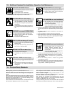
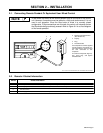
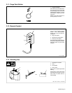
2-1. Connecting Remote Pendant Or Equivalent User-Wired Control
A user-wired equivalent to the remote pendant may be connected to the control
unit. However, connections must be made for a Stop push button even if it is not
used in unit operation. Since the Stop button is wired in a normally closed
configuration, if Stop connections are not made, the control unit interprets that as
the Stop button being continually pressed. Refer to Figure 8-1 for a circuit diagram
of the remote pendant.
NOTE
sb7.1* 5/94 – Ref. ST-162 479-A / Ref. ST-146 839 / Ref. S-0446-A
1 Remote Pendant
2 Remote 4 Receptacle RC3
(See Section 2-2)
3 Keyway
4 Plug
5 Threaded Collar
Use receptacle to connect supplied
remote pendant. User-wired con-
trols equivalent to remote control
are also connected to this
receptacle.
To connect to receptacle, align key-
way, insert plug, and tighten
threaded collar.
DA
CB
1
4
5
23
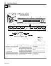
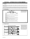
2-2. Remote 4 Socket Information
A Normally closed contact with socket C, opens when pendant Stop button is pressed.
B Normally open contact with socket C, closes when pendant Decrease button is pressed.
C Circuit common.
D Normally open contact with socket C, closes when pendant Start/Increase button is pressed.
Socket InformationSocket