


OM-842 Page 23
11. If applicable, define the program number (see Section
5-1C). Define the shielding gas preflow time as desired.
The range for preflow is 0.0 to 25.0 seconds, in incre-
ments of 0.1 seconds.
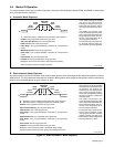
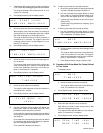
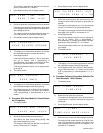
12. Press Right/Increase, and the display shows:
#0X START LEVEL
T I ME=.XXX AMPS=XXX.X
13. Define the start level time and amperage as desired.
When properly used, start level eases arc starting by
allowing the use of an amperage value that is higher
than initial amperage for a short length of time.
The range for start level time is 0.0 to 15.0 seconds, in
increments of 0.1 seconds. The range for start level
amperage varies from 2.0 to 400 amperes, in incre-
ments of 1.0 amperes.
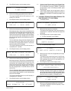
14. Press Right/Increase, and the display shows:
#0X INITIAL
T I ME=XX.X AMPS=XXX.X
15. Define the initial current level time and amperage val-
ues as desired.
The range for initial current level time is 0.0 to 25.0 sec-
onds, in increments of 0.1 seconds. The range for initial
current level amperage varies from 2.0 to 400 am-
peres, in increments of 1.0 amperes.
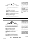
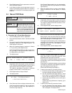
16. Press Right/Increase, and the display shows:
#0X INITIAL SLOPE
TIME=XX.X
17. Define the initial slope time as desired.
The range for initial slope time is 0.0 to 25.0 seconds, in
increments of 0.1 seconds.
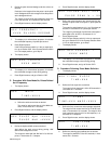
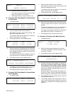
18. Press Right/Increase, and the display shows:
**PULSE MODE IS**
>XXX<
19. Pressing Parameter Select toggles the display be-
tween pulse mode On and pulse mode Off. Three
possibilities exist at this point, as follows:
Pulse mode On is desired and pulses are to be defined
as time spent in peak current and background current
(see Step 20).
Pulse mode On is desired and pulses are to be defined
as a frequency, with peak current defined as a percent-
age of the total period (see Step 20).
Pulse mode Off is desired (see Step 21).
20. To define pulse mode On, proceed as follows:
a. Be sure the desired means of defining pulse mode
has been selected according to Section 2-4.
b. Use the Parameter Select push button to select
pulse mode On, and press Right/Increase to ad-
vance to the next display while ”On” is displayed.
c. If pulses are being defined as time values, go to
Section 5-2B.
If pulses are being defined as a frequency, go to
Section 5-2C.
21. To define pulse mode Off, proceed as follows:
a. Use the Parameter Select push button to select
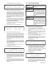
pulse mode Off, and press Right/Increase while
”Off” is displayed. The display shows:
#0X WELD
T IME=XXX.X AMPS=XXX.X
b. Define the weld current time and amperage values
as desired.
The range for weld current time is 0.0 to 999.9 sec-
onds, in increments of 0.1 seconds. The range for
weld current amperage varies from 2.0 to 400 am-
peres, in increments of 1.0 amperes.
c. Press Right/Increase, and go to Section 5-2D.
B. Procedure With Pulse Mode On, Pulses Defined
In Time Values
1. The display shows:
#0X WELD
T IME=XXX.X
a. Define the weld current time as desired.
The range for weld current time is 0.0 to 999.9 sec-
onds, in increments of 0.1 seconds.
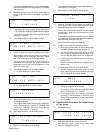
2. Press Right/Increase, and the display shows:
#0X PULSE ApK =XXX.X
PULSE AbK =XXX.X
3. Define the ApK and AbK values as desired.
ApK defines the peak current during pulsing. AbK
defines the background current.
The ranges for both ApK and AbK are 2.0 to 400 am-
peres, in increments of 1.0 ampere.
4. Press Right/Increase, and the display shows:
#0X PEAK T IME =X.XX
B A C K T I M E = X .X X