


OM-842 Page 16
SECTION 4 – INTRODUCTION TO PROGRAMMING
4-1. General
Programs are created when parameters are defined in a series of displays. Up to four programs can be entered into each of the four
modes of operation, for a total of sixteen programs. In addition, programs in certain modes can be linked or combined to run in a
user-defined sequence.
This welding power source provides high frequency or scratch starting, preflow timing, start current level control and timing, initial
current level control and timing, initial slope timing, final slope timing, final current level control and timing, postflow timing, and am-
perage control of weld/peak current for either a pulsing or nonpulsing weld current. Pulsing controls include on/off selection, pulse
peak level control and timing, background current level control and timing, and pulse frequency and average current calculations.
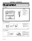
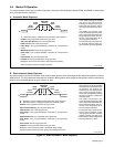
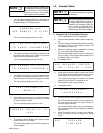
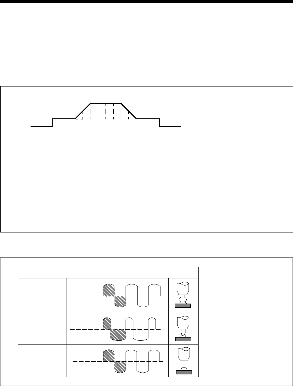
4-2. Weld Sequence
Ref. SB-139 983
In most cases, the weld sequence
shown here is used in programming
the control. Which steps are pro-
grammable and what initiates each
step varies from mode to mode.
Initial
Current
Weld/Peak
Current
Initial
Slope
Final
Slope
Final
Current
Preflow
Postflow
Preflow: The period during which shielding gas flows before an arc is
established.
Start Level (Not Shown): A current level that can be programmed to ease
arc starting.
Initial Current: The beginning maintained current level.
Initial Slope: The ramping of the initial current up to the programmed weld/
peak current level.
Weld/Peak Current: The programmed weld current level (divided into peak
and background current levels when pulsing is enabled).
Final Slope: The ramping down of weld/peak current to the programmed final
current level.
Final Current: The end current level just before the arc is extinguished.
Postflow: The period during which shielding gas flows after the arc has been
extinguished.
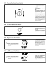
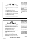
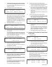
4-3. Balance Control
When ac output is selected on the
Process Selector switch, a balance
control value must be programmed.
The balance control value can be
used to change the weld arc charac-
teristics for either more penetration
or more cleaning. The electrode
negative (EN) value is user-
programmed, and the electrode pos-
itive (EP) value changes accordingly
so the sum always equals 100%.
50% Electrode
50% Electrode
Negative
Positive
Balance Control Waveform Examples
More Cleaning
More Penetration
Balanced
55% Electrode
45% Electrode
Positive
Negative
32% Electrode
68% Electrode
Positive
Negative