


OM-842 Page 11
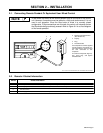
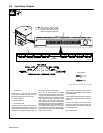
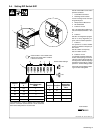
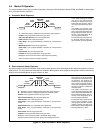
2-4. Setting DIP Switch SW1
Ref. ST-800 194 / Ref. ST-162 477-A
Set DIP switch SW1 rocker switch
positions as follows:
1 Control Box Front Panel
2 Retaining Screw Location
Loosen retaining screw, and open
hinged front panel.
3 Microprocessor Board PC5
4 DIP Switch SW1
5 Positions 7 And 8
Set 7 and 8 according to table to se-
lect Semi-Automatic Modes 1 thru
5.
6 Position 4
Set Off to run diagnostics program.
Set On to stop diagnostics pro-
gram, and for all other operations.
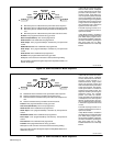
7 Position 3
Use position 3 to select whether
pulses are defined as frequency or
time values.
Set Off to define as frequency.
Set On to define as time.
8 Positions 1 And 2
In Automatic and Semi-Automatic 1
modes, weld amperage can be ad-
justed up or down during weld using
remote pendant. Define amperage
adjustment range limits by setting
positions 1 and 2 according to table.
Close front panel and tighten retain-
ing screw after setting SW1.
1
On
On
Off
Off
On
Off
On
Off
Position
7
Position
8
Defined
Semi-Automatic
Mode
*1
2
3
4
*5On On
*Semi-Automatic 1 mode is defined when remote Stop
switch is connected. Semi-Automatic 5 mode is defined
when remote Stop switch is not connected.
2
4
3
Actual numbers 1 thru 8 below rocker
switches are upside down. Positions
5 and 6 are not used.
Tools Needed:
Position
On
On
Off
Off
On
Off
On
Off
±5 Amperes
±10 Amperes
±20 Amperes
±40 Amperes
1
Position
2
Defined
Amperage
Adjustment
Limit
1
2345678
4
8
5
6
7
= On
Rocker Switch Settings:
= Off