


OM-842 Page 18
Ref. SB-139 983
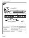
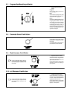
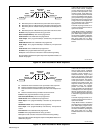
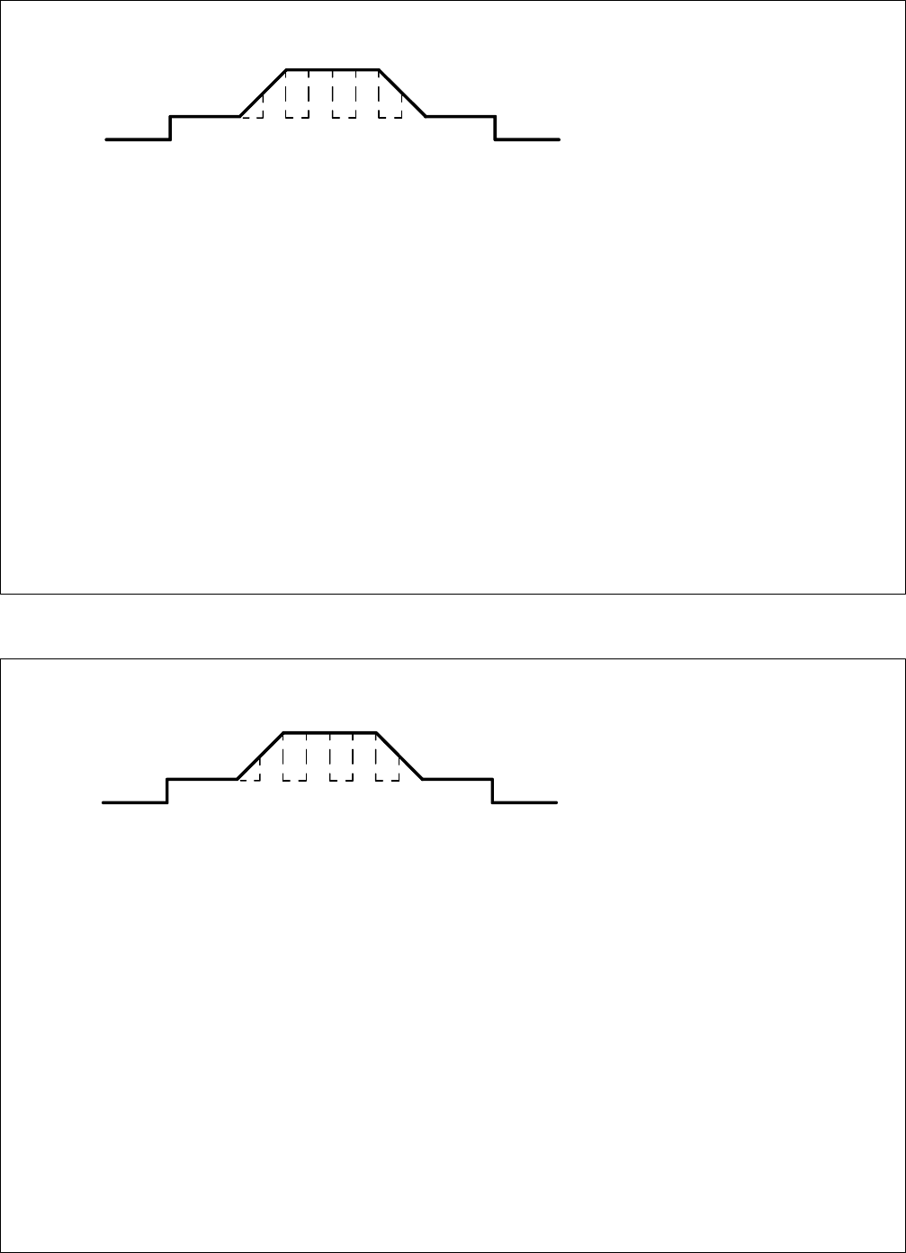
In this mode, time values are not de-
fined for initial current, weld/peak
current, and final current. The micro-
processor control operates in a mo-
mentary-contact, single button for-
mat. The operator presses the Start/
Increase push button to start the pro-
gram, presses it again to signal the
end of initial current, presses it again
to signal the end of weld/peak cur-
rent, and presses it for a last time to
signal the end of final current.
The weld amperage cannot be in-
creased or decreased once the se-
quence has started.
If Stop Button Detect is enabled in
the weld program, pressing the Stop
push button stops program execu-
tion and starts postflow. If Stop But-
ton Detect is disabled, pressing the
Stop push button has no affect.
Postflow starts if the arc is manually
broken.
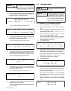
A: Momentary closure of Start/Increase push button starts sequence.
B: Momentary closure of Start/Increase push button ends initial current.
C: Momentary closure of Start/Increase push button ends weld/peak cur-
rent.
D: Momentary closure of Start/Increase push button ends final current.
Preflow: Time programmed/Volume set by gas meter.
Start Level (Not Shown): Time & level programmed.
Initial Current: Time undefined/Level programmed.
Initial Slope: Time programmed/Slope calculated by microprocessor
control.
Weld/Peak Current: Time undefined/Level programmed.
Final Slope: Time programmed/Slope calculated by microprocessor
control.
Final Current: Time undefined/Level programmed.
Postflow: Time programmed/Volume set by gas meter.
Weld/peak current cannot be increased or decreased during welding.
Stop push button functions throughout sequence if Stop Button Detect is en-
abled in the program.
A
Initial
Current
Weld/Peak
Current
Initial
Slope
Final
Slope
Final
Current
Preflow
Postflow
C
B
D
Figure 4-2. Semi-Automatic 2 Mode Sequence
Ref. SB-139 983
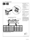
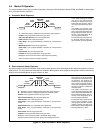
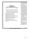
In this mode, time values are not de-
fined for initial current, weld/peak
current, and final current. The micro-
processor control operates in a
maintained-contact, single button
format. The operator presses and
holds the Start/Increase push button
to start the sequence. The Start/In-
crease push button is released to
signal the end of initial current. The
sequence will then cycle through to
weld/peak current. The operator
presses and holds the Start/In-
crease push button to signal the end
of weld/peak current. The sequence
will then cycle through to final cur-
rent. The Start/Increase push button
is released to signal the end of final
current.
The weld amperage cannot be in-
creased or decreased once the se-
quence has started.
If Stop Button Detect is enabled in
the weld program, pressing the Stop
push button stops program execu-
tion and starts postflow. If Stop But-
ton Detect is disabled, pressing the
Stop push button has no affect.
Postflow starts if the arc is manually
broken.
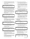
A: Maintained closure of Start/Increase push button starts sequence.
B: Release of Start/Increase push button ends initial current.
C: Maintained closure of Start/Increase push button ends weld/peak cur-
rent.
D: Release of Start/Increase push button ends final current.
Preflow: Time programmed/Volume set by gas meter.
Start Level (Not Shown): Time & level programmed.
Initial Current: Time undefined/Level programmed.
Initial Slope: Time programmed/Slope calculated by microprocessor
control.
Weld/Peak Current: Time undefined/Level programmed.
Final Slope: Time programmed/Slope calculated by microprocessor
control.
Final Current: Time undefined/Level programmed.
Postflow: Time programmed/Volume set by gas meter.
Weld/peak current cannot be increased or decreased during welding.
Stop push button functions throughout sequence if Stop Button Detect is en-
abled in the program.
A
Initial
Current
Weld/Peak
Current
Initial
Slope
Final
Slope
Final
Current
Preflow
Postflow
C
B
D
Figure 4-3. Semi-Automatic 3 Mode Sequence