


OM-842 Page 10
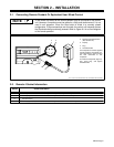
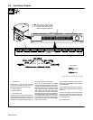
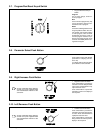
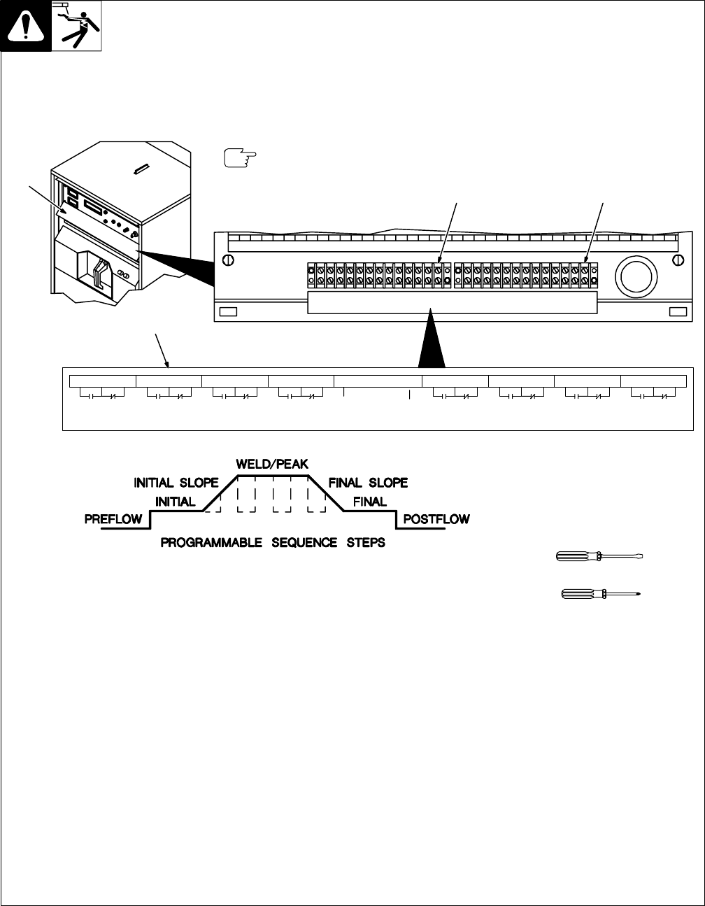
2-3. User Relay Contacts
Ref. ST-162 477-A / ST-162 841 / Ref. SC-159 862
1 Access Door
Access door is hinged at top, and held
closed with industrial interlock strips. To
open, grasp bottom and pull out firmly.
2 Terminal Strip 3T
3 Terminal Strip 4T
4 Connection Label
Use 3T and 4T to connect external equip-
ment to internal relay contacts. Pairs of nor-
mally closed and normally open contacts are
provided for each weld sequence step, the
pulse signal, and for a wire feeder.
Each set of weld sequence contacts
changes state at the beginning of the match-
ing part of the weld sequence, and resets at
the end of postflow. For example, the initial
slope contacts change state when initial
slope begins, and reset at the end of post-
flow. The user relay contacts change state
regardless of the time value programmed for
the matching portion of the weld sequence.
If 0.0 seconds was entered as a time value
for final slope, the user relay contacts match-
ing final slope and final current would change
states at the same time.
The pulse signal contacts change state as
pulsed output goes between peak and back-
ground amperage.
The wire feed contacts operation is program-
mable, and is explained where needed in
Section 5.
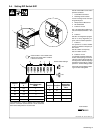
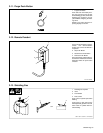
To make connections, route leads through
openings in either side of access door, and
make connections to terminals according to
the connection label.
Close access door.
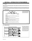
1
ABCDEFGHJKLMN PRSTUVWXYZAABBCC
INITIAL TIME INITIAL SLOPE WELD PEAK FINAL SLOPE FINAL TIME POST FLOW PULSE SIGNAL WIRE FEED
WELD
TIME
CONTACTS
S-157 815
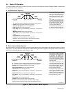
2 3
4
Tools Needed:
Or
The internal control relay
contacts accessible through
terminal strips 3T and 4T are
rated at 20 amperes, 250 volts.