


OM-842 Page 38
2. Turn off welding power source.
3. Turn off shielding gas supply at the source, if applica-
ble.
6-8. Overheating Protection
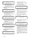
If the unit overheats, the weld sequence goes to postflow and
the contactor is deenergized. The user relay contacts stay in
the state they were in before postflow was entered and remain
that way until postflow ends. The following repeating displays
are shown:
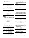
POWER SOURCE
THERMAL OVERLOAD
ALLOW TO COOL
BEFORE CONT I NU I NG
The ammeter and voltmeter displays flash until one of the fol-
lowing events takes place:
1. The thermostat resets (indicating the unit has cooled
down).
2. The operator turns the unit Off and then On again.
3. The operator moves the Program/Run/Reset keyed
switch to the Reset position, then to either Run or Pro-
gram, as applicable.
If the operator carries out items 2 or 3 above, the program pa-
rameters can be viewed or modified, but the unit output
contactor cannot be energized. If the operator tries to energize
the contactor, the unit goes to postflow and repeats the dis-
plays shown above.
If the unit overheats, wait until the unit cools down before start-
ing to weld.
SECTION 7 – DIAGNOSTICS
7-1. Introduction
A. General
The diagnostics program allows the following to be tested:
1. Internal RAM memory
2. Front panel programming push buttons
3. Run and Program positions of the keyed switch
4. Output selector switch
5. Mode selector switch
6. Purge push button
7. Analog output circuitry
8. Output contactor
9. Background relay
10. Gas solenoid relay
11. Arc starter relay
12. User relays, which include the following:
Initial Time relay
Initial Slope relay
Weld Time relay
Final Slope relay
Final Time relay
Postflow relay
Wire Feed Time Delay relay
Pulse Signal relay
13. Remote Pendant
14. Current detection circuitry
15. Input contactor
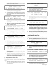
The RAM test and the programming push button tests are car-
ried out each time the diagnostics program is started. The
remaining tests can be performed in sequence, or the Right/In-
crease or Left/Decrease push buttons can be used to access a
desired test. Refer to the subsections in this section for infor-
mation on each test.
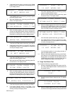
B. Running The Diagnostics Program
To carry out the diagnostics program, proceed as follows:
1. Follow the directions in Section 2-4 for choosing the
diagnostics program on DIP switch SW1.
2. Place Program/Run/Reset keyed switch in Run
position.
3. Energize the unit.
C. Stopping The Diagnostics Program
To stop the diagnostics program, follow the directions in Sec-
tion 2-4 for choosing program execution on DIP switch SW1.