


OM-842 Page 17
4-4. Modes Of Operation
The microprocessor control has four modes of operation: Automatic, Semi-Automatic, Manual GTAW, and SMAW. In abbreviated
form, the modes function as follows:
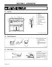
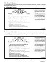
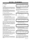
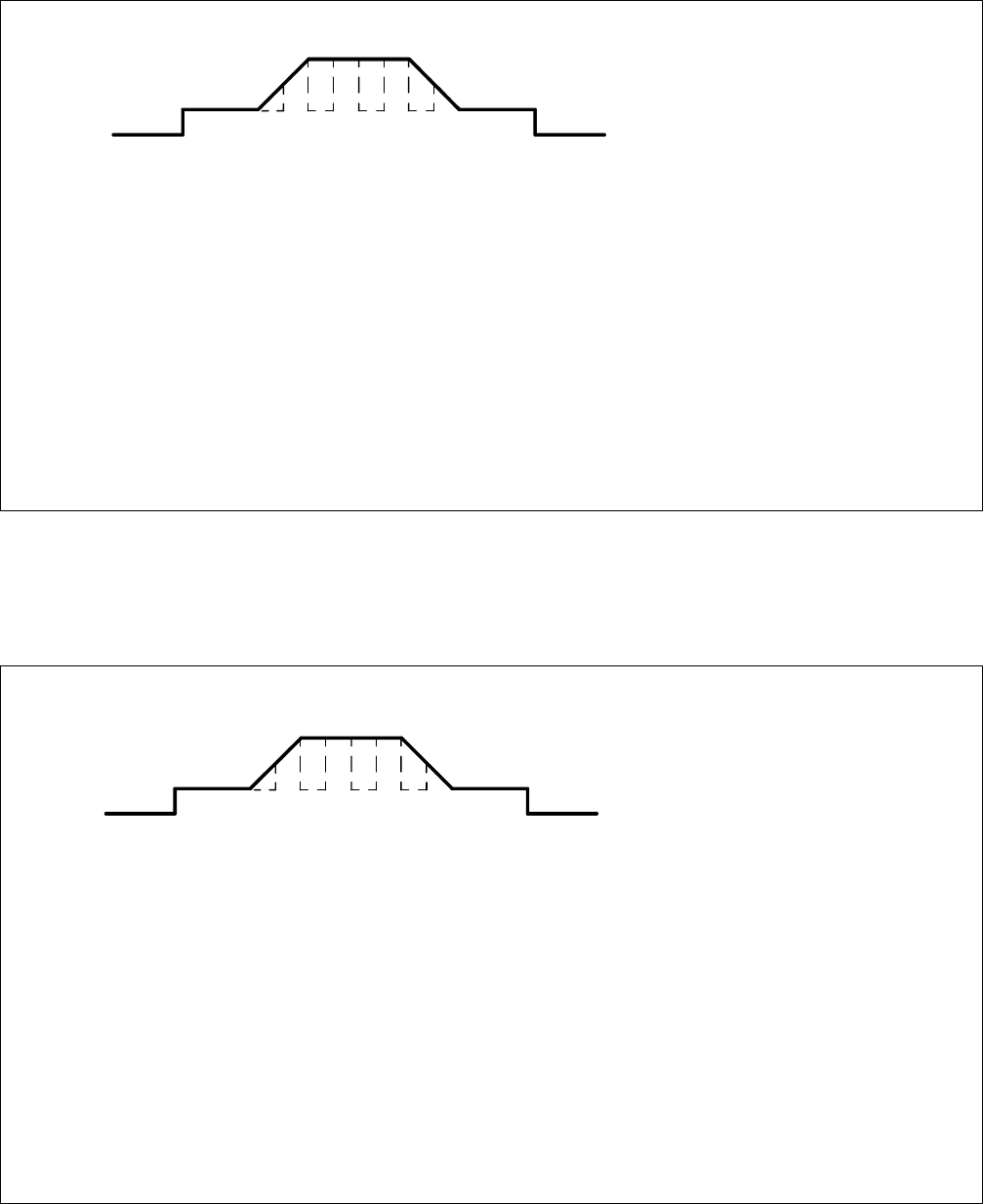
A. Automatic Mode Sequence
Ref. SB-139 983
In this mode, the program controls
each step of the weld sequence.
Pressing the Start/Increase push
button starts the sequence, with no
more input required from the opera-
tor.
The operator can increase or de-
crease weld amperage during weld/
peak current within the defined am-
perage adjustment limits (see Sec-
tion 2-4). This change does not af-
fect the programmed values.
Pressing the Stop push button dur-
ing the weld sequence stops pro-
gram execution and starts postflow.
A: Momentary closure of Start/Increase push button starts sequence.
Preflow: Time programmed/Volume set by gas meter.
Start Level (Not Shown): Time & level programmed.
Initial Current: Time & level programmed.
Initial Slope: Time programmed/Slope calculated by microprocessor
control.
Weld/Peak Current: Time & level programmed.
Final Slope: Time programmed/Slope calculated by microprocessor
control.
Final Current: Time & level programmed.
Postflow: Time programmed/Volume set by gas meter.
Weld/peak current can be increased or decreased during welding.
Stop push button functions throughout sequence.
A
Initial
Current
Weld/Peak
Current
Initial
Slope
Final
Slope
Final
Current
Preflow
Postflow
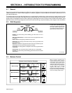
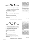
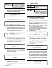
B. Semi-Automatic Mode Sequence
A program created in the Semi-Automatic mode controls certain portions of the weld sequence but requires the operator to control
other portions. The Semi-Automatic mode has five variations. Which portions of the sequence the operator controls, and how the
portions are controlled depends on which variation is used.
Ref. SB-139 983
In this mode, the end time for weld/
peak current is not defined. Pressing
the Start/Increase push button starts
the sequence. The program pro-
ceeds through each step into weld/
peak current. The operator must sig-
nal the end of weld/peak by pressing
the Stop push button, at which time
final slope starts.
The operator can increase or de-
crease weld amperage during weld/
peak current within the defined am-
perage adjustment limits (see Sec-
tion 2-4). This change does not af-
fect the programmed values.
Pressing the Stop push button be-
fore the start of weld/peak current
stops program execution and starts
postflow. Pressing the Stop push
button after the end of weld/peak has
been signalled has no effect.
A: Momentary closure of Start/Increase push button starts sequence.
B: Momentary closure of Stop push button ends weld/peak current.
Preflow: Time programmed/Volume set by gas meter.
Start Level (Not Shown): Time & level programmed.
Initial Current: Time & level programmed.
Initial Slope: Time programmed/Slope calculated by microprocessor
control.
Weld/Peak Current: Time undefined/Level programmed.
Final Slope: Time programmed/Slope calculated by microprocessor
control.
Final Current: Time & level programmed.
Postflow: Time programmed/Volume set by gas meter.
Weld/peak current can be increased or decreased during welding.
Stop push button functions up to the signaled end of weld/peak current.
A
Initial
Current
Weld/Peak
Current
Initial
Slope
Final
Slope
Final
Current
Preflow
Postflow
B
Figure 4-1. Semi-Automatic 1 Mode Sequence