


15
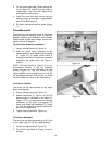
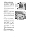
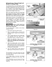
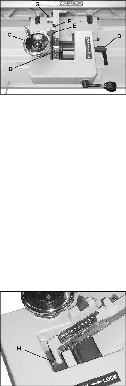
3. Rotate handwheel (C, Figure 16) until the
desired angle is indicated on the scale (D,
Figure 16). Or you can place your beveled
workpiece on the table and against the
fence, and rotate the handwheel (C, Figure
16) until the angle of the fence matches the
bevel of your workpiece.
4. Tighten locking handle (B, Figure 16).
IMPORTANT: When the tilted operation is
finished and the fence is returned to 90°, do not
forget to flip the 90° stop block (F, Figure 16)
back to its original position.
Fence Stops
Periodically check the 90° and 45° tilt accuracy
of the fence with an angle measuring device,
such as an adjustable square or machinist’s
protractor. If adjustments are necessary,
proceed as follows:
Setting the 90° Stop
1. The 90° stop is controlled by the screw (F,
Figure 16) and the stop block (E, Figure 16).
2. Loosen the locking handle (B, Figure 16)
and loosen the hex nut on the screw (F,
Figure 16).
3. Set your angle measuring device to 90
degrees, and place it on the table and
against the fence.
4. Move the fence until it fits flush against the
angle measuring device. Turn the screw (F,
Figure 16) until the screw contacts the stop
block (E, Figure 16).
5. Tighten the hex nut on the screw (F, Figure
16) and the lock handle (B, Figure 16).
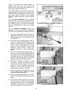
Setting the 45° Forward Stop
1. The 45° forward stop is controlled by the
screw (H, Figure 17).
2. Loosen the locking handle (B, Figure 16)
and loosen the hex nut on the screw (H,
Figure 17).
3. Set your angle measuring device at 45°.
Place it on the table and against the fence,
and tilt the fence until it is flush against the
45° angle.
4. Rotate the screw (H, Figure 17) until it
contacts the casting in front of it.
5. Tighten the hex nut on the screw (H, Figure
17) and tighten locking handle (B, Figure
16).
Figure 16
Figure 17