


17
Setting Tables Coplanar
For optimum performance of the jointer, the
infeed and outfeed tables must be coplanar; that
is, parallel front-to-back and side-to-side. If they
are not parallel in both planes, the finished
workpiece may have a slight taper across its
width or length.
The tables have been properly aligned at the
factory. However, they should be double-
checked by the operator in case any
misalignment may have occurred during
shipping. Also, as the machine receives use,
this coplanarity should be checked occasionally
and adjusted if necessary.
The following procedure uses a steel straight
edge to set the tables, which should be accurate
enough for most purposes.
This procedure demonstrates how to set the
parallelism of the outfeed table; the procedure
for the infeed table will be identical.
1. Disconnect jointer from power source.
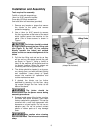
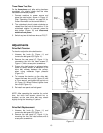
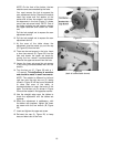
2. Remove the cutterhead guard by loosening
the set screw (see Figure 6) and lifting the
guard shaft out of the hole.
3. Slide the fence assembly back as far as it
will go, or remove it from the machine
entirely (see page 28 for instructions on
removing the fence).
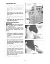
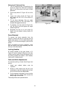
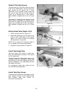
4. Loosen the locking handle on the outfeed
table (see A, Figure 23). Use the lifting
handle (B, Figure 23) to raise the outfeed
table higher than the cutterhead.
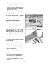
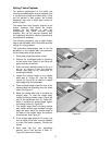
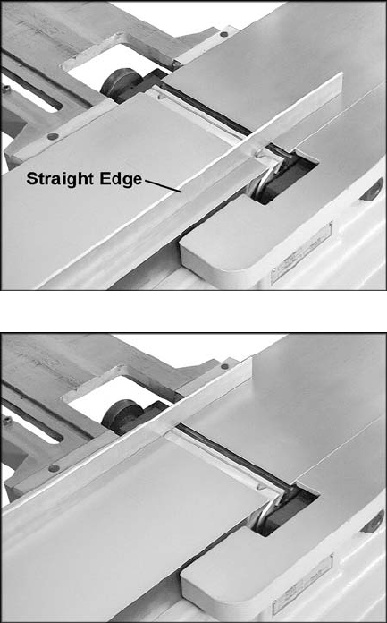
5. Place a straight edge across the front of the
outfeed table and extending over the infeed
table. See Figure 19.
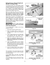
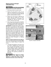
6. Raise the infeed table until it contacts the
straight edge. To raise the infeed table,
loosen the locking handle (see A, Figure 28)
and lift the adjustment arm (B, Figure 28).
When it contacts the straight edge, tighten
the locking handle (A, Figure 28).
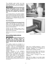
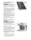
7. The straight edge should lie evenly across
both tables without gaps between straight
edge and table. Move the straight edge to
the back of the outfeed table, and perform
the same test. See Figure 20.
8. If the straight edge does not lie evenly, the
front or back of the table must be adjusted
to make the tables coplanar. Proceed as
follows.
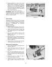
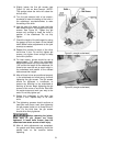
9. Each table has four cam adjustment
devices; two in front and two in back. (C
,
Figure 22 shows one of these).
Figure 19
Figure 20