


16
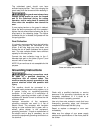
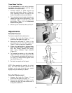
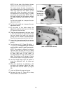
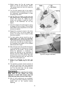
Setting the 45° Backward Stop
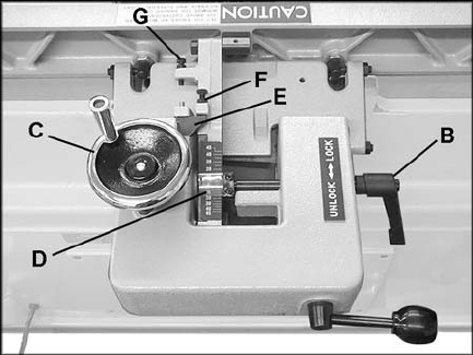
1. The 45° backward stop is controlled by the
screw (G, Figure 18), which will contact the
back of the fence when the fence is tilted
backward.
2. Flip the stop block (E, Figure 18) out of the
way.
3. Loosen the locking handle (B, Figure 18)
and loosen the hex nut on the screw (G,
Figure 18).
4. Tilt the fence backward. Set your angle
measuring device at 135° and place it on
the table and against the fence.
5. If necessary, turn the screw (G, Figure 18),
until the fence lies flush against the angle
measuring device.
6. Re-tighten the hex nut on the screw (G,
Figure 18) and tighten locking handle (B,
Figure 18).
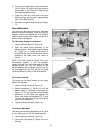
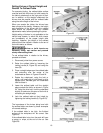
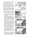
Fence Removal
To remove the fence assembly from the
machine, remove the two hex nuts and one flat
washer that secure it to the slide bracket (see
Figure 15). Lift the fence straight up and off the
Jointer.
When re-installing the fence assembly, make
sure the cutout in the fence assembly sits over
the key in the slide bracket.
Locking Handles
All locking handles of the type shown in B,
Figure 18, can be rotated if they are in the way
of other machine parts. Simply lift straight out on
the locking handle and rotate it, then release,
making sure it seats properly.
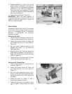
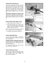
Table and Knife Adjustments
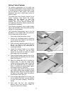
For accurate jointing, at least three things must
be true:
1. Infeed and outfeed tables must be
“coplanar”.
2. Knives or knife inserts must be set in the
cutterhead so that the highest point of their
arc is level with the the outfeed table.
3. On the standard cutterhead, knives must be
parallel with the outfeed table across the
entire length of the knives.
These alignments are explained below.
Figure 18