


21
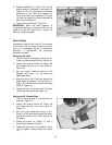
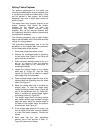
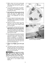
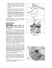
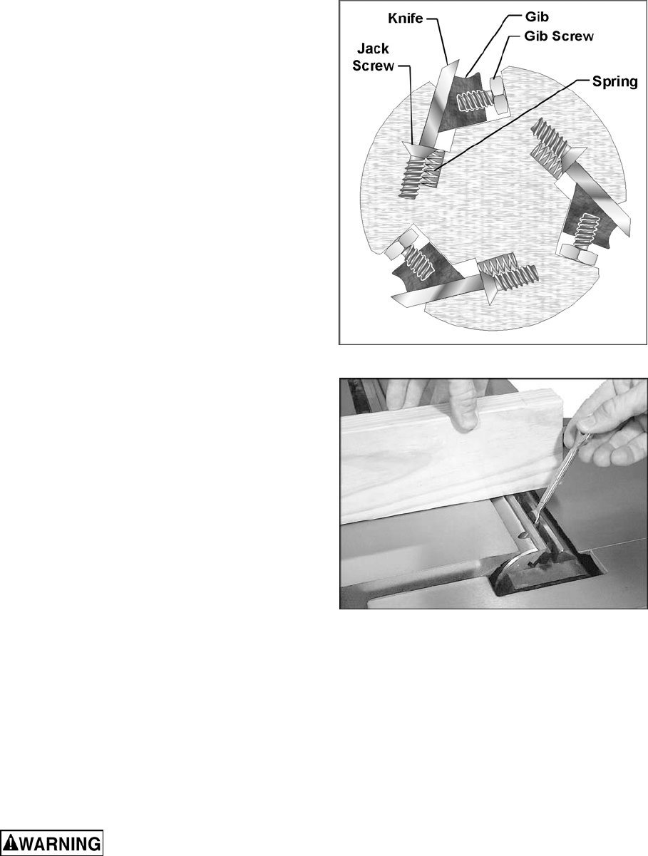
14. Slightly loosen the five gib screws (see
Figure 31) with an 8mm wrench. (NOTE:
The springs below the knife will cause the
knife to rise.)
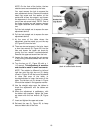
15. Turn the jack screw(s) with a hex wrench;
clockwise to lower the setting of the knife in
the cutterhead, counterclockwise to raise
the setting of the knife.
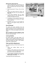
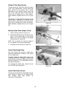
16. Use the edge of a board to push the knife
back down so that it is flush against the jack
screws. See Figure 32. Tighten the gib
screws only enough to keep the knife in
position in the cutterhead. Do not fully
tighten.
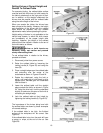
17. Check the height of the knife again by using
the gauge at front and back of the outfeed
table. Make further adjustments to the jack
screw(s) as needed.
18. Repeat this process for each of the other
two knives in turn. Do not fully tighten gib
screws, only tighten them enough to keep
the knife in position.
19. For best results, knives should be set at
approximately .015" above the cutterhead.
Knife height should not vary more than .002-
.003" across the length of the cutterhead. All
three knives must be set at equal height in
the cutterhead and parallel to the outfeed
table across their length.
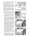
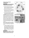
20. After all three knives are positioned properly
in the cutterhead and made snug, continue
tightening the gib screws. The gib screws
should be tightened in increments, to
prevent any distortion to the cutterhead or
buckling of knives. Begin tightening the gib
screws a little more on one knife. Start with
the center screw and work your way to the
ends. Do not fully tighten yet.
21. Rotate the cutterhead to the other two
knives in turn. Repeat step 19 for each
knife.
22. The tightening process should continue at
least two more times, each time tightening
the gib screws further on all three knives in
turn. On the third time, the gib screws
should all be firmly tightened.
Before operating the jointer,
make sure all gib screws are firmly
tightened. A loose knife thrown from the
cutterhead can cause severe or fatal injury.
23. After all knife adjustments are completed,
the guards and fence assembly should be
placed back on the machine before
operating.
Figure 31 (straight cutterhead)
Figure 32 (straight cutterhead)