


18
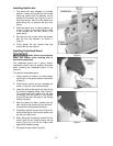
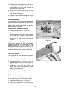
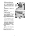
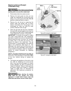
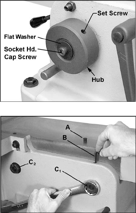
NOTE: On the front of the Jointer, the two
outside cams are concealed by the hubs.
You must remove the hub to expose the
cam adjustment device. Remove the socket
head cap screw and flat washer at the
center with a 6mm hex wrench, and loosen
the setscrews in the hub (Figure 21 shows
one of two set screw holes). NOTE: One of
the holes contains two set screws; remove
the upper setscrew and loosen the lower
one.
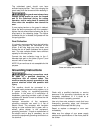
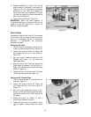
Pull the hub straight out to expose the cam
adjustment device.
10. Pull the hub straight out to expose the cam
adjustment device.
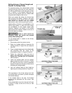
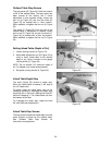
11. At the area of the table where the
adjustment must be made, pry out the cap
(A, Figure 22) from the hole.
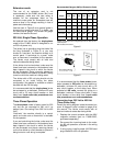
12. There are two set screws in the hole. Insert
a 4mm hex wrench (B, Figure 22) into the
hole and loosen the upper set screw by
turning the hex wrench counterclockwise.
Remove the upper set screw from the hole.
13. Loosen the lower set screw (do not remove
it) by turning counterclockwise with the hex
wrench.
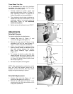
14. Turn the hex nut (C
1
, Figure 22) with a 1-
1/4" wrench. This adjustment is sensitive
and should be made in small increments.
NOTE: The rotation is different for left and
right hex nuts; the right hex nut (C
1
) being
turned in Figure 22 will be turned clockwise
to raise that area of the table, or
counterclockwise to lower that area of the
table. The left hex nut (C
2
) shown in Figure
22 would be rotated in the opposite manner.
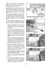
15. Use the straight edge upon the tables to
check the adjustment until the tables are
coplanar.
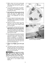
16. When the adjustment is satisfactory, with
the tables now coplanar, tighten the lower
set screw with the hex wrench (B, Figure
22).
17. Insert and tighten the upper set screw.
18. Re-insert the cap (A, Figure 22) to keep
dust and debris out of the hole.
Figure 21
Figure 22
(back of outfeed table shown)