


8
Po werware 9350 Series 685 and 1085 Auxiliary Battery Cabinets
Installation Manual 164201408 Rev. P00 053002
FRONT
SIDE
FOAM
SUPPORT
SUPPORT
1
2
1
2
2
2
JACKING
BOLT
(Step 2)
FLOOR
PROTECTOR
(Step 2)
1
2
LEFT HAND
DOOR
CUSHION
(Step 1)
(Step 3)
(Step 8)
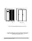
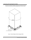
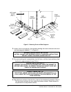
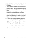
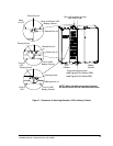
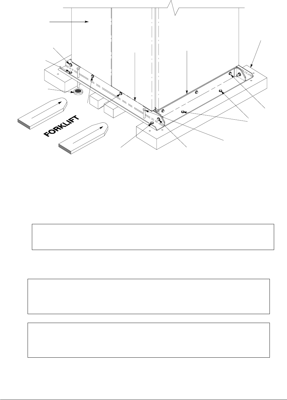
Figure 5. Removing Front and Rear Supports
3. Loosen, but do not remove, the hardware holding the foam cushions to the front
and rear supports (labeled “1” in Figure 5).
WARNING: SERIOUS INJURY MAY OCCUR!
BATTERY CABINETS ARE EXTREMELY HEAVY. IF UNLOADING INSTRUCTIONS
ARE NOT CLOSELY FOLLOWED, CABINET MAY TIP.
4. Turn each jacking bolt consecutively, two full turns, until the foam cushions clear
the floor by approximately 3 mm (1/8 in.).
DANGER: RISK OF INSTABILITY!
TURNING THE JACKING BOLTS UNEVENLY MAY CAUSE THE CABINET TO
BECOME UNBALANCED. TO PREVENT TIPPING THE CABINET, RAISE AND
LOWER THE JACKING BOLTS EVENLY.
DANGER: CABINET MAY TIP!
THE BATTERY CABINET SHOULD ONLY BE RAISED APPROXIMATELY 3 mm
(1/8 in.) ABOVE THE FLOOR (JUST ENOUGH TO ALLOW REMOVAL OF THE
FOAM CUSHIONS).
5. After the foam cushions clear the floor, remove the hardware loosened in Step 3.
Pull the foam cushions out from under the b attery cabinet. Please discard or
recycle them in a responsible manner.