


34
Po werware 9350 Series 685 and 1085 Auxiliary Battery Cabinets
Installation Manual 164201408 Rev. P00 053002
You should read and understand these general notes before beginning installation:
• The material and labor for external wiring requirements is to be supplied by
others.
• Power cables and control wiring must be installed in separate conduit.
• The ground conductor is to be sized per NEC Article 250 and local electrical
code requirements.
• The maximum current listed is at the minim um DC operating voltage.
• Nominal voltages listed in this chapter are for a lead-acid battery plant rated per
NEC at 2.00 VDC per cell.
• Battery cabinets must be installed in accordance with all applicable codes and
regulations, including the National Electrical Code (NEC), Article 480.
• The UPS to battery cable should be sized for a total maximum voltage drop of
1% nominal DC link voltage at maximum current.
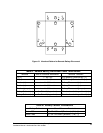
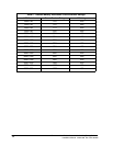
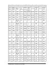
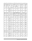
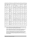
• The external wiring specifications are outlined in Table C of Appendix A. Tables
A and B in this chapter detail the power cable terminations.
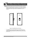
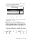
• The remote battery disconnect weighs approximately 11.4 kg (25 lb) and has an
ampere interrupting capacity of 10,000 at 500 VDC.
• Tightening Torque: 28.7 --- 31.1 N-M (255---275 lb-in.)
Internal Drive Hex Size: 5/16 in.
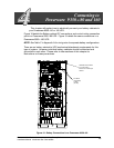
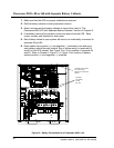
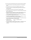
• The knockout pattern for conduit is shown in Figure 21. If a larger size conduit
is required, the contractor may enlarge knockouts at your site during
installation.