


25
Po werware 9350 Series 685 and 1085 Auxiliary Battery Cabinets
Installation Manual 164201408 Rev. P00 053002
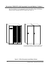
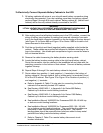
To Electrically Connect Separate Battery Cabinets to the UPS:
1.
All battery cabinets will arrive at your site with each battery connection string
electrically disconnected. If you are installing more than one battery cabinet,
perform Steps 2 through 6 for each cabinet. Battery cabinet #1 (the left-hand
cabinet) will be the only cabinet directl y connected to the UPS.
WARNING:
LETHAL VOLTAGE WILL BE PRESENT WHEN PERFORMING THE RE MAINING
STEPS IN THIS SECTION AND SUBSEQUENT SECTIONS.
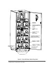
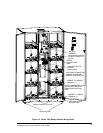
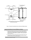
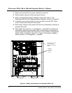
2. After making sure that all battery breakers are in the OFF position, connect the
string of battery trays together by mating the loose red connector from each
tray to the fixed black connector mounted on the front edge of the tray above it
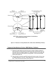
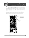
(see Figure 10 for Series 685 and Figure 13 for Series 1085 for location of all
items discussed in this section).
3. Find the red (positive) and black (negative) cables supplied coiled inside the
cabinet. These cables are provided half-stripped to facilitate attaching to the
lugs in the cabinet. Use double pole compression lugs to secure the wires to
the unit terminal blocks.
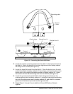
4. Remove the cable tie securing the battery breaker sensing cable.
5. Locate the battery breaker sensing cable in the right-hand battery cabinet.
Route this connector into the cabinet to the immediate left and mate with the
matching connector in the b ottom of that cabinet. Connect all battery cabinets
together this way.
6. Repeat Steps 2 through 5 for each battery cabinet to be joined.
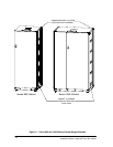
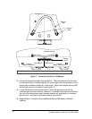
7. Route cables from positive (+) and negative (---) terminals in the bottom of
battery cabinet #1 through conduit (top or bottom entry) to terminals E4 and
E5oftheUPScabinet. SeeFigure10orFigure12forlocationofpositive(+)
and negative (---) terminals.
a. R efer to Appendix A, Tabl e C to size wire for connecting the battery
cabinets to the remotely located UPS cabinet.
b. See Drawing 164201408---1 in Appendix A for Series 685 Battery
Cabinet top or bottom conduit landing locations.
c. See Drawing 164201408---2 in Appendix A for Series 1085 Battery
Cabinet top or bottom conduit landing locations.
d. See Installation Manual 164200253 for Powerware 9350 30---80 kVA top
or bottom conduit landing locations.
e. See Installation Manual 164200292 for Powerware 9350 100---160 kVA
top or bottom conduit landing locations. The conduit landing plates are
removable to add conduit landing holes as required. The conduit
landing pl ates should be removed w hen holes are added to keep metal
particles from falling inside the battery cabinet.
f. Refer to Chapter 5, Table C for r em ote battery disconnect circuit
breaker information.