


22
Po werware 9350 Series 685 and 1085 Auxiliary Battery Cabinets
Installation Manual 164201408 Rev. P00 053002
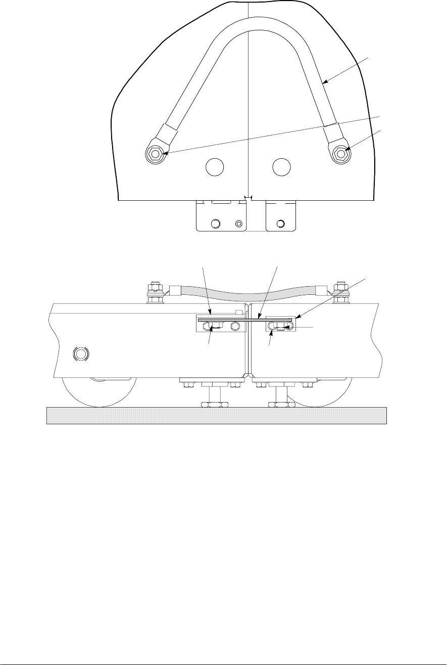
Nut from kit
Screw from kit
Front of
Battery Cabinet #2
Bracket from kit
Nut from kit
Bracket from kit
Front of
Battery Cabinet #1
Existing hinge
Grounding cable
Ground
Studs
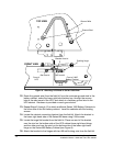
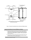
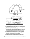
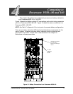
Figure 15. Connecting Two Series 685 Bases
3. Locate the cabinet connecting bracket and two M4×10 hex head screws from
the field kit. Attach the bracket to the lower right-hand side of battery cabinet
#2 using the two screws (see Figure 15) .
4. Locate the large flat bracket fro m the field kit. Place the bracket over the stud
on the bottom side of battery cabinet #1 lower hinge, and over the stud on the
bottom side of the cabinet connecting bracket on battery cabinet #2. Attach
the bracket with two M8 self - locking nuts from the field kit (see Figure 15).
5. Locate the ground wire from the fiel d kit. Route the ground wire from the
customer ground stud in battery cabinet #1, under the lower right-hand battery
tray, into the cable access area in battery cabinet #2, and attach to customer
ground stud. Hardware is provided on each ground stud.
6. Repeat Steps 1 through 5 to join additional Series 685 Battery Cabinets
together.