


A --- 10
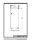
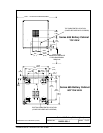
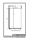
Po werware 9350 Series 685 and 1085 Auxiliary Battery Cabinets
Installation Manual 164201408 Rev. P00 053002
DESCRIPTION:
DRAWING NO:
1of1
SHEET:
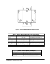
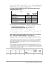
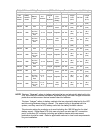
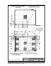
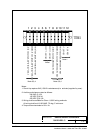
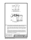
Remote Interface Connections
164201408--3
1
CB1 AUXILIARY SWITCH (N/C)
CB1 AUXILIARY SWITCH (COMM)
CB1 AUXILIARY SWITCH (N/O)
CB1 ST (--) C11
CB1 ST (+) C12
CB1 AUXILIARY SWITCH (N/C)
CB1 AUXILIARY SWITCH (COMM)
CB1 AUXILIARY SWITCH (N/O)
CB1 ST (--)
CB1 ST (+)
TB1
Notes:
1. Shunt trip requires 24V (150 VA instantaneous) to activate (supplied by user).
2. Auxiliary switches are rated as follows:
240 VAC @ 15A
125 VDC @ 0.3A
250 VDC @ 0.15A
3. Wiring shall be suitable for Class 1, 600V wiring methods.
Note 2,3,4 Note 2,3,4
Note 1
Note 1
4. Torque screw t erminals to 20 in.-lb.
All wiring shall be #10-22 A WG, 75 deg. C minimum.
23456789 1110 12