


A---11
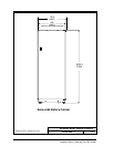
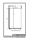
Po werware 9350 Series 685 and 1085 Auxiliary Battery Cabinets
Installation Manual 164201408 Rev. P00 053002
DESCRIPTION:
DRAWING NO:
1of1
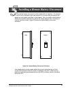
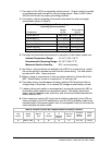
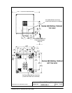
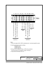
Series 685 / 1085 Co nfigurations
SHEET:
164201408--4
BATTERY
CABINET
BATTERY
CABINET
UPS
CABINET
(E4)
BATTERY
CABINET
BATTERY
CABINET
UPS
CABINET
BATTERY
DISCONNECT
Powerware 9350 30 through 160
Battery Cabinets integral to UPS
and connected using Manufacturer supplied wiring
Battery Cabinets located separately
4 Cabin ets Maximum
4 Cabin ets Maximum
Contractor Wiring (2): See
Table C of Appendix A to size
Contractor Supplied wiring
CONTRACTOR
WIRING (2)
CONTRACTOR
WIRING (1)
Contractor Wiring (1): Refer to UPS manual to size wiring
(E5)
(E4)
(E5)
Powerware 9350 30 through 160
from the UPS
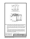
NOTE: The term “Se parate” refers to battery cabinets that are not physically attached
to the UPS, are wired with external contractor supplied wiring, and use a single
overcurent protection and disconnect device located near the batteries.
The term “Integral” refers to battery cabinets that are physically attached to the
UPS and the wiring between them is internal. The power wiring is supplied
with the system, and they use the UPS battery switch as the battery isolation
device.
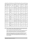
Thewiresizeratingforproductsuptoandincludingthe160/160areforthe
total battery supply. Since these UPS units can only land one wire per DC
connection point, a common DC collector including an isolation device and
overcurrent protection should be used. Refer to applicable national or local
code requirements for your installation.