


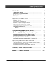

iii
Po werware 9350 Series 685 and 1085 Auxiliary Battery Cabinets
Installation Manual 164201408 Rev. P00 053002
ATTENTION:
Une batterie peut prêsenter un risque de choc êlectrique, de brulure, ou d’incen-
die. Suivre les précautions qui s’imposent.
• Pourleremplacement,utiliserlemêmenombreetmodéledesbatteries.
• L’élimination des batteries est règlementée. Consulter les codes locaux à cet
effet.
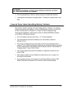
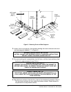
General Notes About Installing Battery Cabinets
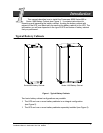
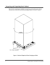
Each battery cabinet is packed and crated separately for shipping. You should
unpack and inspect each cabinet, roll it to its final position, and join it to the UPS
or other cabinets (refer to Chapter 3 or Chaper 4) before installing wiring.
These general installation notes apply to either the Series 685 Battery Cabinet
or the Series 1085 Battery Cabinet:
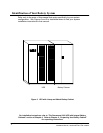
• Do not tilt battery cabinets more than 10˚ during installation.
• The recommended minimum clearance over each battery cabinet is
305 mm (12 in.).
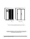
• The conduit landing plates are removable to add conduit landing holes as
required. The conduit landing plates should be removed w hen holes are added
to keep metal particles from falling inside the battery cabinet. Plate material is
16 gauge steel (1.5 mm, 0.06 in. thick).
• Low voltage signal wiring must be installed in a separate conduit fro m the
power wiring.
• Each battery cabinet can be installed as a stand-alone unit or as part of a
redundant joined system.
• The instantaneous trip circuit b reakers for the Series 685 and Series 1085
Battery Cabinets must remain set at minimum ( ful l counterclockwise).