


23
Po werware 9350 Series 685 and 1085 Auxiliary Battery Cabinets
Installation Manual 164201408 Rev. P00 053002
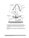
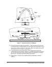
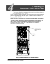
(see detail at left)
Large bracket goes here
Two small brackets go here
(see Figure 17)
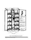
NOTE: When cabinets are properly aligned, all cabinet doors
willbeflushwitheachother.
BAT TERY
CABINET #2
BAT TERY
CABINET #1
Back of
Bracket from kit
Battery Cabinet #2
Back of
Battery Cabinet #1
Existing Screw
Existing Screw
Screw from kit
Screw from kit
Front of
Battery Cabinet #2
Front of
Battery Cabinet #1
Bracket from kit
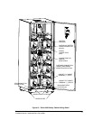
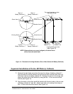
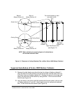
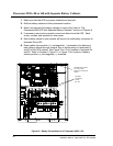
Figure 16. Placement of Joining Brackets (Two or More Series 1085 Battery Cabinets)
Separate Installation of Series 1085 Battery Cabinets
1. Remove the right-hand screw from the top door hinge of battery cabinet #1.
Align the hole in one flat bracket over this screw hole, and the other hole over
the hole in the top of battery cabinet #2. Replace the screw in the hinge, and
attach the other end of the bracket by using an M4×10 hex screw from the
field kit (see Figure 16) .
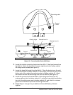
2. Align the holes in the other small flat bracket with the two holes in the top rear
of battery cabinets #1 and #2. Attach each end to its mating hole using an
M4×10hexscrewfromthefieldkit(seeFigure16).