


Operator Manual, Supercharger 60 R3.0
Page 18 of 62
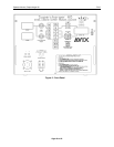
4. CONTROLS AND DISPLAYS
4.1 M1 - Ammeter
4.1.1. 0 to 199.9ADC DIGITAL PANEL METER.
4.1.2. Positive sign indicates charge current.
4.1.3. Minus sign indicates discharge current.
4.2 M1 - Voltmeter
4.2.1. 0 to 1.999VDC, 0 to 19.99VDC and 0 to 199.9VDC DIGITAL PANEL METER.
4.2.2. Indicates battery voltage in the internal (20/200V) position and voltage present at
the RED (+) and BLK (-) jacks in the 2/20/200V external positions. Positive sign
indicates proper battery connection. Minus sign indicates reversed polarity
connection.
4.3 R1 - Main Charge Current Selector
4.3.1. Ten turn potentiometer with digital readout to program: current
4.3.1.1. MAIN charge current, 0 to 50.0 AMPS.
4.4 R2 - Topping/Discharge Current Selector
4.4.1. Ten turn potentiometer with digital readout to program:
4.4.1.1. TOPPING charge current, 0 to 50.0 AMPS
4.4.1.2. DISCHARGE current, 0 to 60.0 AMPS
4.5 SW1 - Main Time selector switch
4.5.1. 0 to 9 hours (or minutes), to determine the duration of the main charge.
4.6 SW2 - Total Time selector switch
4.6.1. 0 to 60 hours (or minutes), to determine the total charge or discharge duration.
4.7 SW3 – Keypad
Five station membrane push button control switch to select and control the mode of
operation, as follows:
4.7.1. GREEN: Stop/reset, cycle end.
4.7.2. WHITE: Two rate charge mode (main and topping).
4.7.3. YELLOW: Single rate charge mode.
4.7.4. BLUE: Auto cut-off discharge (analysis).
4.7.5. RED: Full discharge (deep cycle).