


Operator Manual, Supercharger 60 R3.0
Page 50 of 62
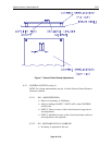
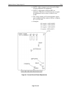
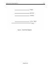
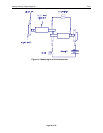
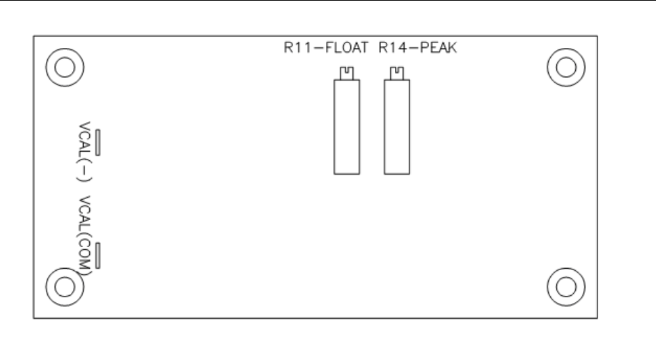
Figure 10 - Voltage Control Board Adjustments
9.2.5.2. VOLTAGE CONTROL - See [Figure 10]
9.2.5.2.1. R11, FLOAT VOLTAGE:
• Connect a CAL-100 Calibrator or a power supply
capable of producing at least 10V (very little current
required) to the CAL (-) and CAL (COMMON) test
points. The positive lead to COMMON and the
negative lead to CAL (-).
• Set the calibrator/power supply to 2.70V to simulate
a battery that has 27.0V.
•
NOTE: The Calibrator voltage is 1/10 of the
simulated battery voltage.
• Connect a battery to the Charger-Analyzer.
• Set the Voltage Control Mode Switch to CV
(Constant Voltage)
• Program for 10A of Topping current.
• Enter 24 in the cell selector (nominal battery
voltage).
• Start the Charger-Analyzer in Single rate. The
current will rise to the programmed 10A.
• Increase the power supply voltage towards 2.8V and
observe the current.
• The charging current will begin to decrease at about
2.75V and should reach zero as the voltage is
advanced to 2.8V.
• NOTE: Ignore the actual battery voltage. The Float
voltage control circuit is responding to the simulated
battery voltage as provided by the power supply.