


Operator Manual, Supercharger 60 R3.0
Page 4 of 62
TABLE OF FIGURES
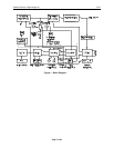
Figure 1 - Block Diagram ...................................................................................................................................... 7
Figure 2 - Front Panel .......................................................................................................................................... 20
Figure 3 - Line Voltage Wiring, 115V ................................................................................................................ 33
Figure 4 - Line Voltage Wiring, 208/230V ......................................................................................................... 34
Figure 5 - Line Voltage Wiring, 230/245V ......................................................................................................... 34
Figure 6 - Meters Board Adjustments .................................................................................................................. 44
Figure 7 - Control Switch Board Adjustments .................................................................................................... 45
Figure 8 - Current Control Board Adjustments ................................................................................................... 47
Figure 9 - Monitor Board Adjustments ................................................................................................................ 48
Figure 10 - Voltage Control Board Adjustments ................................................................................................. 50
Figure 11 - Circuit Board Sequence .................................................................................................................... 52
Figure 12 - Measuring for a shorted transistor ..................................................................................................... 56
Figure 13 - Location of Current Limiters ............................................................................................................ 57
Figure 14 - Power Block Diagram ....................................................................................................................... 58
TABLE OF TABLES
Table 1 - Constant Voltage and Peak Voltage Chart ........................................................................................... 31
Table 2 - Index of Revisions ................................................................................................................................ 62