


11
FEATURES
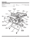
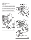
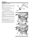
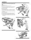
KNOW YOUR TABLE SAW
See Figure 3.
The safe use of this product requires an understanding of
the information on the tool and in this operator’s manual as
well as a knowledge of the project you are attempting. Before
use of this product, familiarize yourself with all operating
features and safety rules.
15 AMP MOTOR WITH SOFT START - The saw has a
powerful 15 amp motor with sufficient power to handle
tough cutting jobs. It is made with all ball bearings, and
has externally accessible brushes for ease of servicing.
ANTI-KICKBACK PAWLS - Kickback is a hazard in which
the workpiece is thrown back toward the operator. The teeth
on the anti-kickback pawls point away from the workpiece.
If the workpiece should be pulled back toward the operator,
the teeth dig into the wood to help prevent or reduce the
possibility of kickback.
BEVEL SCALE - The easy-to-read scale on the front of the
workstand shows the exact blade angle.
BLADE - For maximum performance, it is recommended
that you use the 10 in. carbide tipped combination blade
provided with your saw. The blade is raised and lowered
with the height/bevel adjusting handwheel. Bevel angles are
locked with the bevel locking lever. Additional blade styles
of the same high quality are available for specific operations
such as ripping. Your local dealer can provide you with
complete information.
WARNING:
Do not use blades rated less than the speed of
this tool. Failure to heed this warning could result
in personal injury.
BLADE GUARD - Always keep the guard down over the
blade for through-sawing cuts.
BLADE HEIGHT LOCK KNOB - This knob, in the center
of the height/bevel adjusting handwheel, locks the blade
in place.
BEVEL LOCKING LEVER - This lever under the worktable
surface on the front of the cabinet, locks the angle setting
of the blade.
HEIGHT/BEVEL ADJUSTING HANDWHEEL - Located
on the front of the cabinet, this handwheel is used to lower
and raise the blade for adjustments or blade replacement.
The handwheel also makes the adjustment for bevel angles
easy.
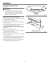
IND-I-CUT™ ALIGNMENT DISC - A plastic insert on which
marks may be made to indicate the location of the cut on
the workpiece.
LOCKING LEVER - The lever on the front of the rip fence
releases the rip fence or locks it in place.
MITER GAUGE - This miter gauge aligns the wood for a
cross cut. The easy-to-read indicator shows the exact angle
for a miter cut, with positive stops at 0˚ and 45˚.
MITER GAUGE GROOVES - The miter gauge rides in these
grooves on either side of the blade.
RAILS - Front and rear rails provide support for the rip
fence.
RIP FENCE - A sturdy metal fence guides the workpiece
and is secured with the locking lever. Grooves run along the
top and sides of the rip fence for use with optional clamps
and accessories.
SCALE - Located on the front rail, the easy-to-read scale
provides precise measurements for rip cuts.
SPREADER- A metal piece of the blade guard assembly,
slightly thinner than the saw blade, which helps keep the
kerf open and prevent kickback.
SWITCH ASSEMBLY - This saw has an easy access
power switch located below the front rail. To lock the switch
in the OFF position, remove the yellow switch key from the
switch. Place the key in a location that is inaccessible to
children and others not qualified to use the tool.