


39
ADJUSTMENTS
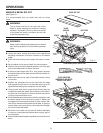
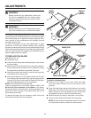
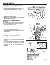
TO ADJUST THE BEVEL LOCKING LEVER
See Figure 57.
Release bevel locking lever and bevel saw blade to 45º.
Push bevel locking lever to lock blade into place.
With moderate force, attempt to move the height/bevel
adjusting handwheel toward the 0º bevel.
If height/bevel adjusting handwheel cannot be moved,
no adjustment is needed. If handwheel can be moved,
adjust the bevel lock nut by rotating clockwise 1/4 turn.
Repeat above step as necessary.
Release bevel locking lever and move height/bevel
adjusting handwheel back to 0º.
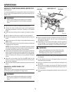
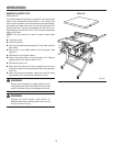
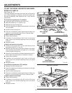
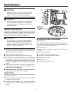
CHECKING THE TABLE EXTENSION
See Figure 58.
Lock the sliding table extension. The sliding table extension
should not move while locked. If the extension moves:
Lift the table extension lock lever.
Find the front hex coupling located underneath the front
table.
Loosen the hex locking nut.
Turn the hex coupling counterclockwise.
Lock the table extension lock. Push and pull on the sliding
table extension.
Readjust hex coupling if necessary.
Tighten the hex locking nut against coupling.
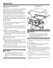
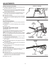
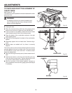
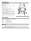
TO ADJUST THE TABLE EXTENSION
See Figure 59.
Lock table extension lever.
Loosen the four nuts underneath the sliding table
extension.
Use a combination square to make sure the top of the
sliding table extension is the same height as the main
table.
Tighten the four hex nuts. Recheck and readjust if
necessary.
Fig. 57
Fig. 58
Fig. 59
HEX
LOCKING
NUT
BEVEL LOCK NUT
COMBINATION
SQUARE
HEX NUT
EXTENSION
TABLE
FRONT HEX
COUPLING