


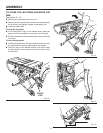
25
5
0
1
2
4
6
7
3
2
3
4
5
6
7
8
9
10
OPERATION
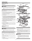
TO SET THE RIP FENCE INDICATOR TO THE
BLADE
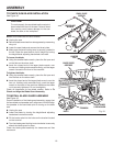
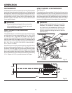
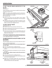
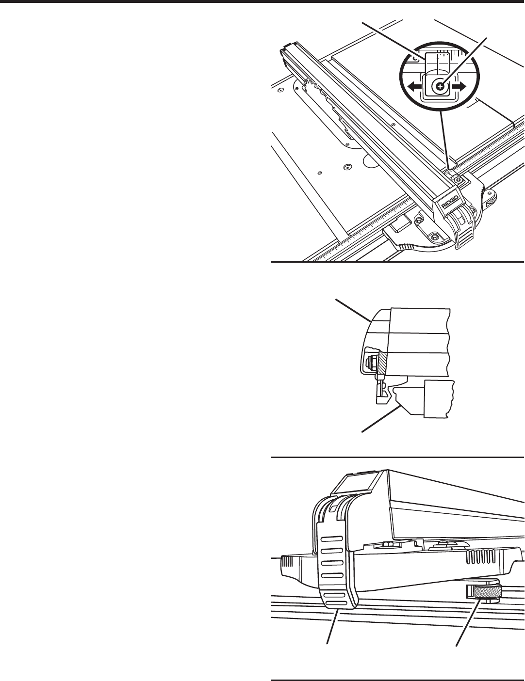
See Figure 27.
Use the indicator on the rip fence to position the fence along
the scale on the front rail.
NOTE: The blade guard assembly must be removed to
perform this adjustment. Reinstall the blade guard assembly
when the adjustment is complete.
Unplug the saw.
Place the rip fence on the saw table so that it lightly
touches the right side of the saw blade. Lock the rip fence
in place.
Loosen pan head screw and adjust the indicator so that
the red line is located over the “zero” line on the right rip
scale on the front rail. Retighten screw.
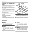
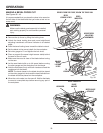
TO USE THE RIP FENCE
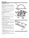
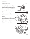
See Figures 28 - 29.
Place the front of the rip fence on the front rail.
Lower the back end of the rip fence onto the back rail.
Check for smooth gliding action.
Push the locking lever down to automatically align and
secure the fence. When securely locked, the locking lever
should point downward.
Check for a smooth gliding action. If adjustments are needed,
see To Check and Adjust the Alignment of the Rip Fence
in the Adjustments section of this manual.
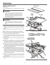
TO USE THE MICRO-ADJUST WHEEL ON THE
RIP FENCE
See Figure 29.
The micro-adjust wheel on the rip fence allows the user to
make one-handed adjustments.
To use the micro-adjust wheel on the right-hand side of
the saw blade:
Unlock the locking lever by lifting the lever.
Push in on the micro-adjust wheel and rotate to the desired
location.
Push the locking lever downward to lock the rip fence
into place.
To use the micro-adjust wheel on the left-hand side of
the saw blade:
Unlock the locking lever by lifting the lever.
Turn the rip fence over and remove the two phillips screws
on the micro-adjust bracket.
Rotate the micro-adjust bracket 180° and reinstall the
phillips screws. The rip fence is now set up to be used
on the left-hand side of the saw blade.
Fig. 27
PAN HEAD
SCREW
INDICATOR
Fig. 29
MICRO-ADJUST
WHEEL
Fig. 28
BACK RAIL
BACK OF
RIP FENCE
LOCKING
LEVER
0
1