


38
®
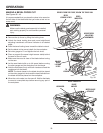
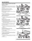
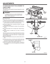
TO CHECK AND ADJUST THE ALIGNMENT OF
THE RIP FENCE
See Figures 54 - 56.
The rip fence must be parallel to the saw blade and the miter
gauge grooves.
WARNING:
A misaligned rip fence can cause kickbacks and
jams. To reduce the risk of injury, always maintain
proper rip fence alignment
Unplug the saw.
Move the rip fence along side the miter gauge groove
and lock the rip fence in place with the locking lever.
If the rip fence is not parallel, loosen the four hex head
bolts located to each side of the locking handle.
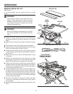
Place the blade of the combination square in the right
miter gauge groove.
Slide the rip fence against the blade of the combination
square.
Alternately tighten the hex head bolts. Recheck align-
ment.
Repeat steps as needed until rip fence is correctly
aligned.
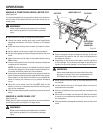
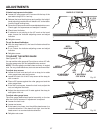
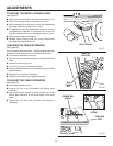
The locking lever on the rip fence should hold the rip fence
securely against the front and back rails. The lever should
not be difficult to push down and lock. To assure proper
fence lock adjustment:
Raise the locking lever and push rip fence toward rear of
saw.
Hold rip fence down on the front rail while lifting the rear
of the rip fence up and down. Tighten adjusting nut until
the rip fence clamp barely touches the rear rail.
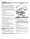
With the rip fence in the locked position, recheck rip
fence parallelism with the miter gauge groove and adjust
if necessary.
ADJUSTMENTS
Fig. 54
Fig. 56
Fig. 55
LOCKING LEVER
HEX HEAD
BOLT
ADJUSTING
NUT
BACK RAIL
LOCKING
LEVER
15
0
30
0
0
3
3
2
2
4
4
5
6
7
8
9
15
14
13
12
11
10
9
1
1
8
10
11
12
13
14