


24
OPERATION
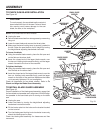
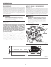
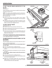
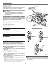
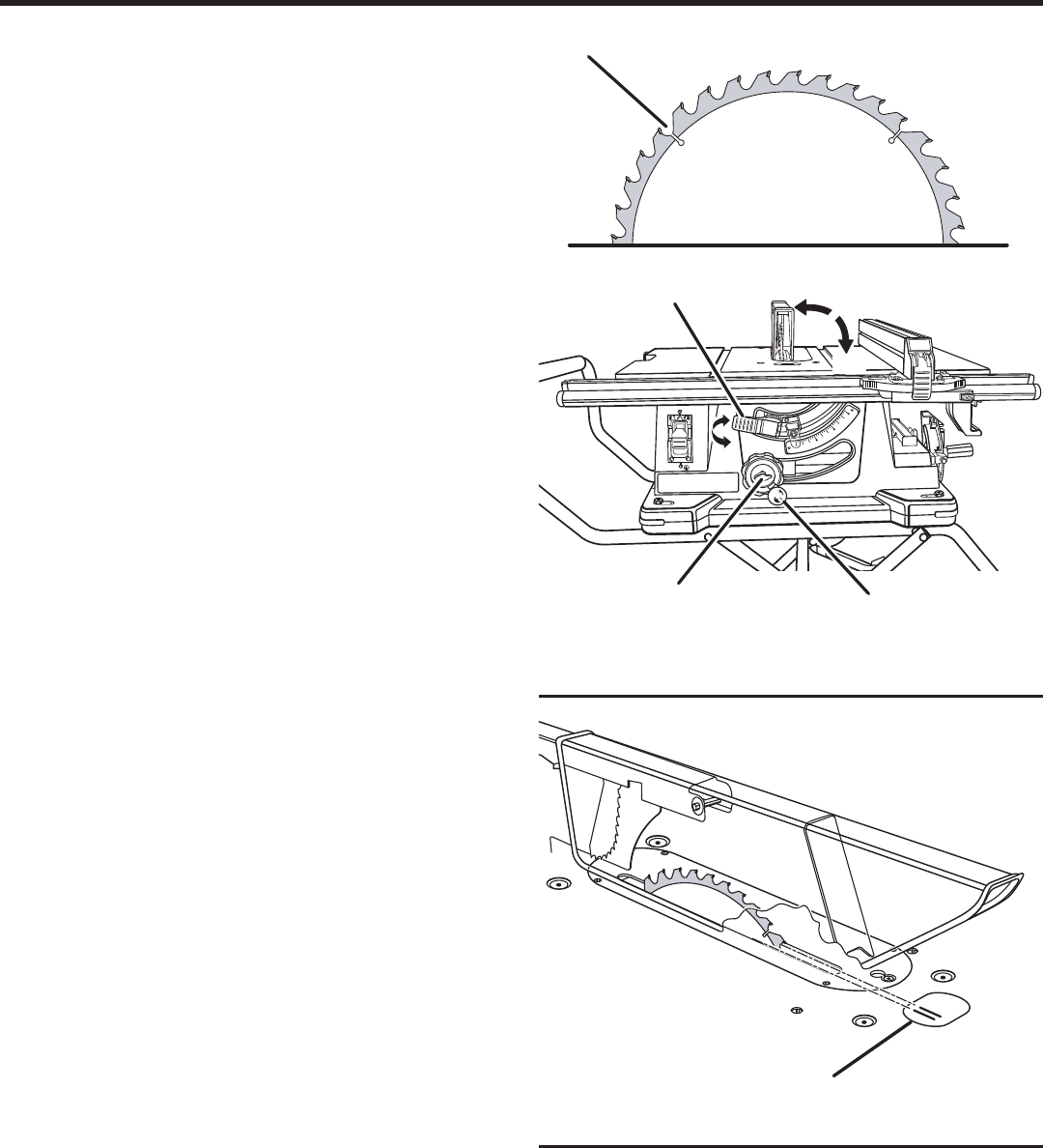
TO CHANGE BLADE DEPTH
See Figure 25.
The saw blade depth should be set so that the outer points
of the saw blade are higher than the workpiece by approxi-
mately 1/8 in. to 1/4 in. but the lowest points (gullets) are
below the workpiece.
Loosen the blade height lock knob by turning it counter-
clockwise.
Raise the saw blade by turning the height/bevel adjusting
handwheel clockwise or lower it by turning the handwheel
counterclockwise.
Once the desired saw blade height is achieved, lock the
blade height lock knob by turning it clockwise.
TO CHANGE BLADE ANGLE
See Figure 25.
NOTE: A 90° cut has a 0° bevel and a 45° cut has a 45°
bevel.
Unlock bevel locking lever by pushing lever all the way
to the right.
Adjust the bevel angle by moving the height/bevel adjusting
handwheel along the bevel scale.
Lock bevel locking lever by pushing lever to the left.
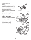
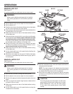
TO USE THE IND-I-CUT DISC
See Figure 26.
The plastic disc embedded in the saw table in front of the
saw blade is provided for marking the location of the saw
cut (kerf) on the workpiece.
The disc should be level or slightly below the surface of the
saw table. Place a piece of hardwood over the plastic disc
and tap the hardwood with a hammer until the disc is level
or below the saw table surface.
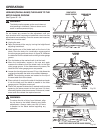
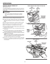
Once the Ind-I-Cut is level:
From the front of the table saw, place the miter gauge in
the left miter groove and move the height/bevel adjusting
handwheel until the bevel scale is set at 0°.
Turn on the table saw and cross cut a piece of wood
holding the wood firmly against the miter gauge.
Turn off the table saw. Once the blade has stopped, pull
the miter gauge back until the freshly cut wood is over
the disc.
Using a sharp pencil, mark a line on the disc at the edge
of the freshly cut wood.
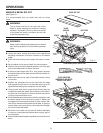
NOTE: These lines indicate the path of the cut made by
the saw blade. When the blade is changed, these lines
will need to be erased and reset.
With the miter gauge in the right miter gauge groove,
follow the above procedures and make a second mark
on the disc.
Fig. 25
BEVEL
LOCKING LEVER
HEIGHT/BEVEL
ADJUSTING
HANDWHEEL
BLADE HEIGHT
LOCK KNOB
Fig. 26
IND-I-CUT
DISC
0°
GULLET
0
15
30
45
ON
OFF
45°