


6 INCRA Woodworking Tools & Precision Rules
Figure 9
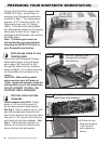
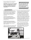
INSTALLING THE ULTRA BASE
Figure 10
Figure 11
Figure 12
1
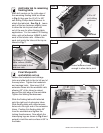
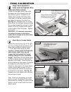
Remove endcap from base
support panel
Remove the (2) fasteners that secure
the endcap to one end of the base
support panel and remove the endcap.
See Fig. 9.
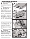
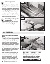
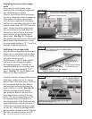
2
Attach the Ultra base to
base support panel
Open hardware pack B-07.
Place #10 washers on each of the (6)
#10-32 x ½” Phillips pan head screws.
Insert four of the screws through the
slotted holes on the Ultra base and
loosely thread a #10-32 hex nut onto
each screw. Insert the remaining two
screws through the two inside holes
located in the middle of the Ultraʼs base
and attach hex nuts. Slide the hex nuts
on all six screws into the T-slots on the
base support panel. The (4) screws/
nuts in the slotted holes slide into the
outer T-slots. The (2) screws/nuts inside
the Ultraʼs base slide into the inner T-
slots. See Fig. 10.
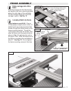
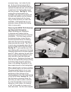
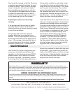
Position the Ultraʼs base on the base
support panel as shown in Fig. 11.
(Edge of the Ultra base should be about
3 ¼” from the end of the panel.) Use
a square to align the Ultra base at 90˚
to the panel and tighten only the four
screws installed in the slotted holes.
Do not tighten the two screws inside the
Ultraʼs base at this time. Replace the
base support panel end cap removed
earlier.
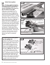
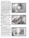
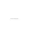
3
Attach base support panel
to floating table.
Using the (2) ¼-20 x 1 ½” threaded
knobs with washers, attach the base
support panel to the floating table as
shown in Fig. 12. Visually align the
leading edge of the base support panel
parallel with the grooves in the top of the
floating table and tighten the threaded
knobs.
Base support
panel
End cap
2 fasteners
mentioned in Fig. 11 below
slide into inside T-slots
4 screws/nuts for slotted holes on
Ultra base slide into outer T-slots
Do not tighten these 2 screws at this time
Square Ultra base to support panel and tighten fasteners
¼-20 x 1 ½” threaded
knobs with washers
¼-20 x 1 ½” threaded
knobs with washers
3¼”