


42.
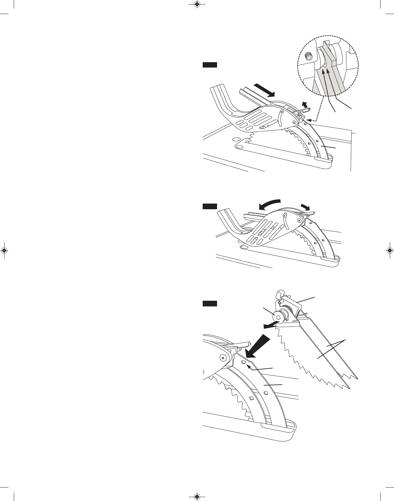
FIG. 22
4
5
FIG. 23
9
8
11
10
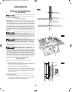
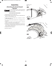
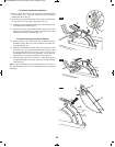
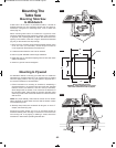
ATTACHING THE GUARD ASSEMBLY
8.With one hand, hold the front of the barrier guard assembly 4
by the metal “fork”. With the other hand, hold the guard
release lever 5 up (Fig. 21).
9.Lower the rear of guard assembly and slip the cross bar 6 into
t
he rear notch 7 on top of the riving knife 2 (Fig. 21).
10. Lower the front of the guard assembly 4 until the metal “fork”
i
s parallel with the table (Fig. 22).
11. Press down on the guard release lever 5 until you feel and
h
ear it snap into the locking position. Check that the guard
assembly is securely connected (Fig. 22).
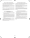
ATTACHING THE ANTI-KICKBACK DEVICE
12. While pulling out the attachment pin 8, attach the Anti-
Kickback Device 9 into the flat recessed area 10 of the
riving knife 2 (Fig. 23).
13. Slide the Anti-Kickback Device down until it drops into the
recessed area – then release the attachment pin such that
the Anti-Kickback Device locks onto the riving knife
immediately behind the guard assembly. Check that the
attachment pin is securely connected into locking hole.
14. Carefully raise and lower the pawls 11 – when letting go, the
spring-loaded pawls must come down and contact the table
insert (Fig. 23).
Note: The two attachments are independent of each other, so
the Anti-Kickback Device can be attached before the Guard
Assembly.
FIG. 21
4
5
7
6
2
2
SM 2610008289 02-10:3310 Table Saw 2/2/10 8:38 AM Page 42