


52.
A
ttachment/Removal
(
see page 40 for detailed instructions)
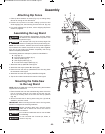
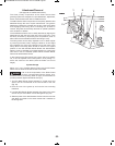
The three primary components of the Smart Guard blade
guarding system are designed for rapid attachment, adjustment,
and/or removal without the need for additional tools.
The Main Barrier Guard component can be quickly attached and
detached through the use of a quick release lever. The guard is
attached by seating the crossbar into the top of the Riving Knife
and engaging the locking lever. Following this process in
reverse, the guard can be easily removed for special operations
such as dados or rabbets.
The Anti-Kickback Device can be easily attached by aligning the
a
ttachment pin with the hole in the rear of the riving knife. It can
be easily removed by depressing the compression pads on
either side of the Anti-Kickback Device and lifting it away.
The Riving Knife can be easily adjusted to one of three heights
by removing the table insert, raising the blade to its full height
and releasing the riving knife release lever at the base of the
Riving Knife. The Riving Knife should be locked in its highest
position for use with the Main Barrier Guard and Anti-Kickback
Device. It can be adjusted to its middle position for non-through
cuts and for use as a material splitter without the Main Barrier
Guard and Anti-Kickback Device.
In the event that the Riving Knife can not be used for a specific
cut, it can be adjusted to its lowest position, thus placing it 1”
above the surface of the table (while the blade is at its full
height).
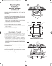
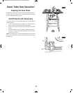
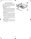
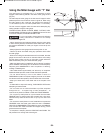
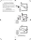
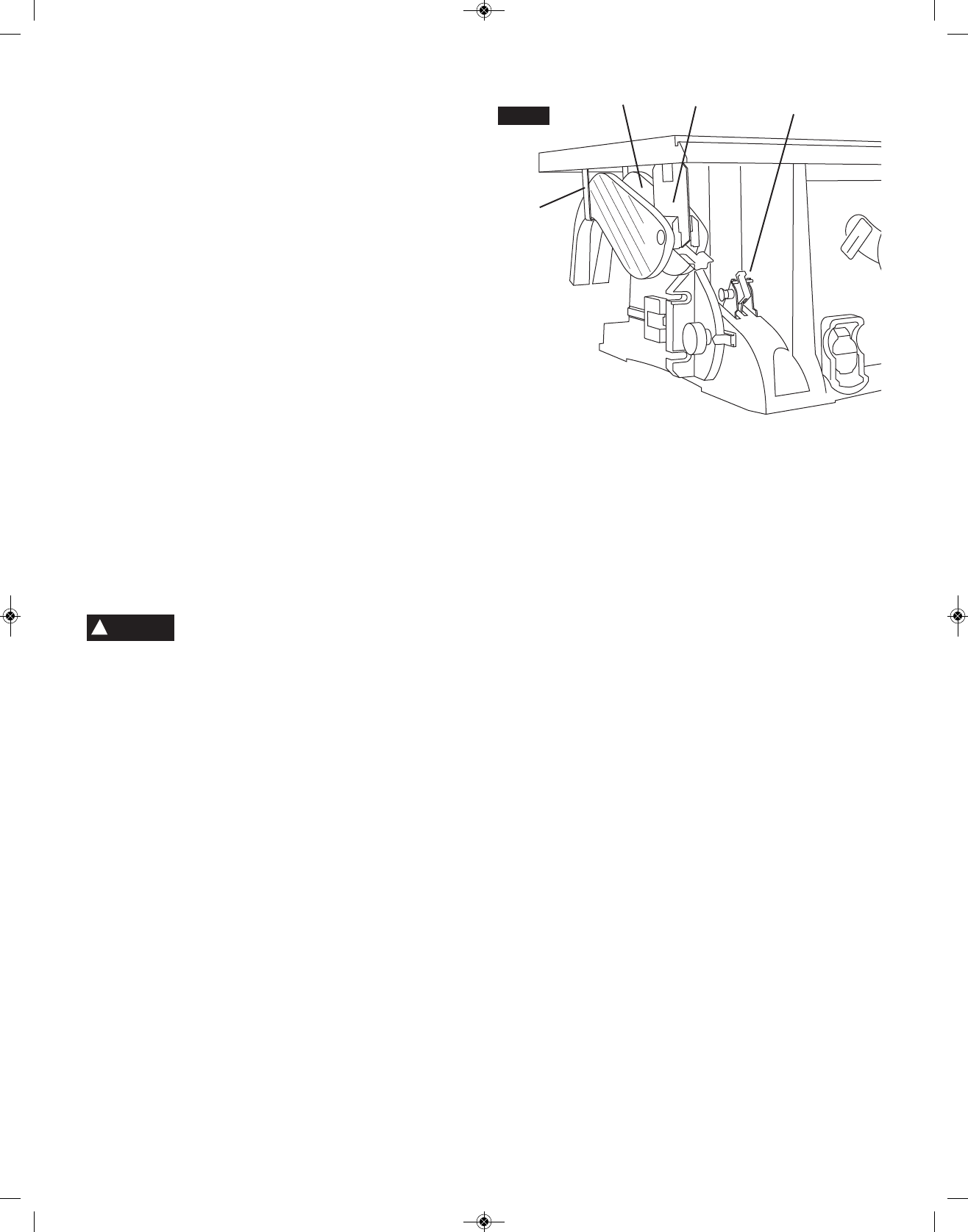
System Storage
When not in use, the Main Barrier Guard and Anti-Kickback
Device can be stored under the left side of the table.
Use of all the components of the Smart Guard
System, including Main Barrier Guard, Anti-
Kickback Device, and Riving Knife is highly recommended to
provide protection against accidents and injury.
1.Turn the Main Barrier Guard assembly 1 upside down and
slide it into the U-bracket 2 at the rear left side of the saw
(Fig. 33).
2.Pivot the rear of the guard up and into the front mounting
bracket 3.
3.Lock the Main Barrier Guard assembly into place in the same
manner as you would attach it to the Riving Knife (Fig. 33).
4.Slide the pawls of the Anti-Kickback Device 4 into the two slots
and attach to bracket in the same manner that it attaches to
the Riving Knife.
4
1
2
3
F
IG. 33
WARNING
!
SM 2610008289 02-10:3310 Table Saw 2/2/10 8:38 AM Page 52