


For Machines Mfg. Since 8/09 Model SB1029
-17-
PREPARATION
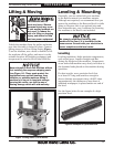
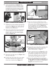
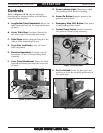
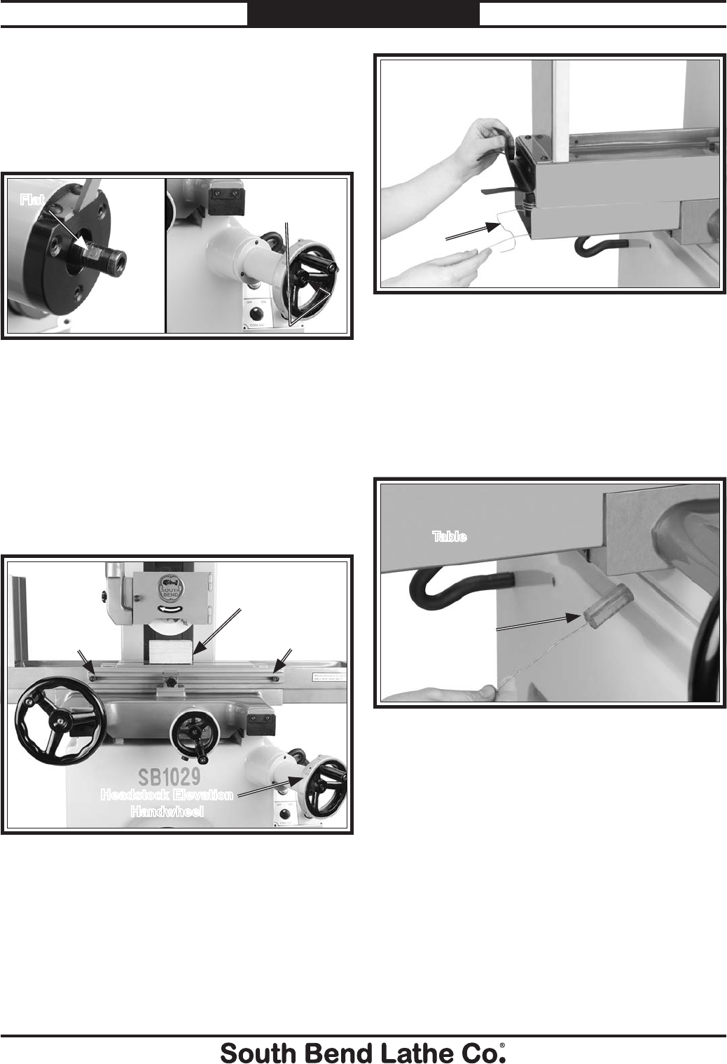
6. Locate the flat shown in Figure 11 on
the headstock elevation handwheel shaft
Next align the set screw on the elevation
handwheel hub with the flat on the shaft,
and slide the handwheel (see Figure 12)
onto the shaft until it stops.
7. Tighten the set screw against the shaft flat,
secure the handwheel to the shaft with the
cap screw (see Figure 11), and install the
handle onto the handwheel.
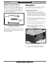
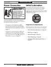
8. Rotate the headstock elevation handwheel
counterclockwise to raise the headstock
slightly, and remove the wooden support
block (see Figure 12).
Figure 12. Table and headstock shipping position.
9. Reposition the table stops (see Figure 12) to
the ends of the table.
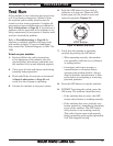
10. At both ends of the table, lift up the rubber
dust skirt, and locate the neoprene seat
wires (two at each end, see Figure 11).
Headstock Elevation
Handwheel
Figure 11. Headstock elevation handwheel.
Flat
Cap
Screw
Table Stop Table Stop
Support
Block
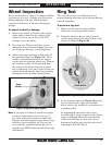
Figure 13. Neoprene shipping seat wires.
Wires
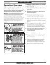
11. Have an assistant carefully lift up on the
table so it is raised approximately an inch or
two, use the wires to pull each neoprene seat
out of its respective way (see Figure 14),
then carefully lower the table onto the ball
bearings. Keep the neoprene seats for future
transport or storage.
12. Repeat this step on the other end of the table
and lubricate the machine as outlined in
Basic Lubrication, on Page 33.
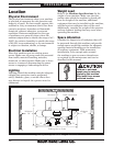
13. Place a precision level (see Figure 8) on the
table surface and adjust the feet studs until
the machine is perfectly level in the X- and
Y-axis, then tighten the jam nuts. Recheck
after 24 hours, and again in two weeks.
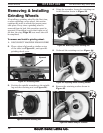
14. Remove the grinding wheel as outlined in
Removing & Installing Grinding Wheels
on Page 23. Next, perform the Ring Test on
Page 22, and reinstall the wheel.
Figure 14. Neoprene shipping seat.
One of Four
Neoprene
Shipping Seats
Table