


For Machines Mfg. Since 8/09 Model SB1029
-41-
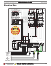
ELECTRICAL
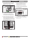
3. Without changing the location of any of the
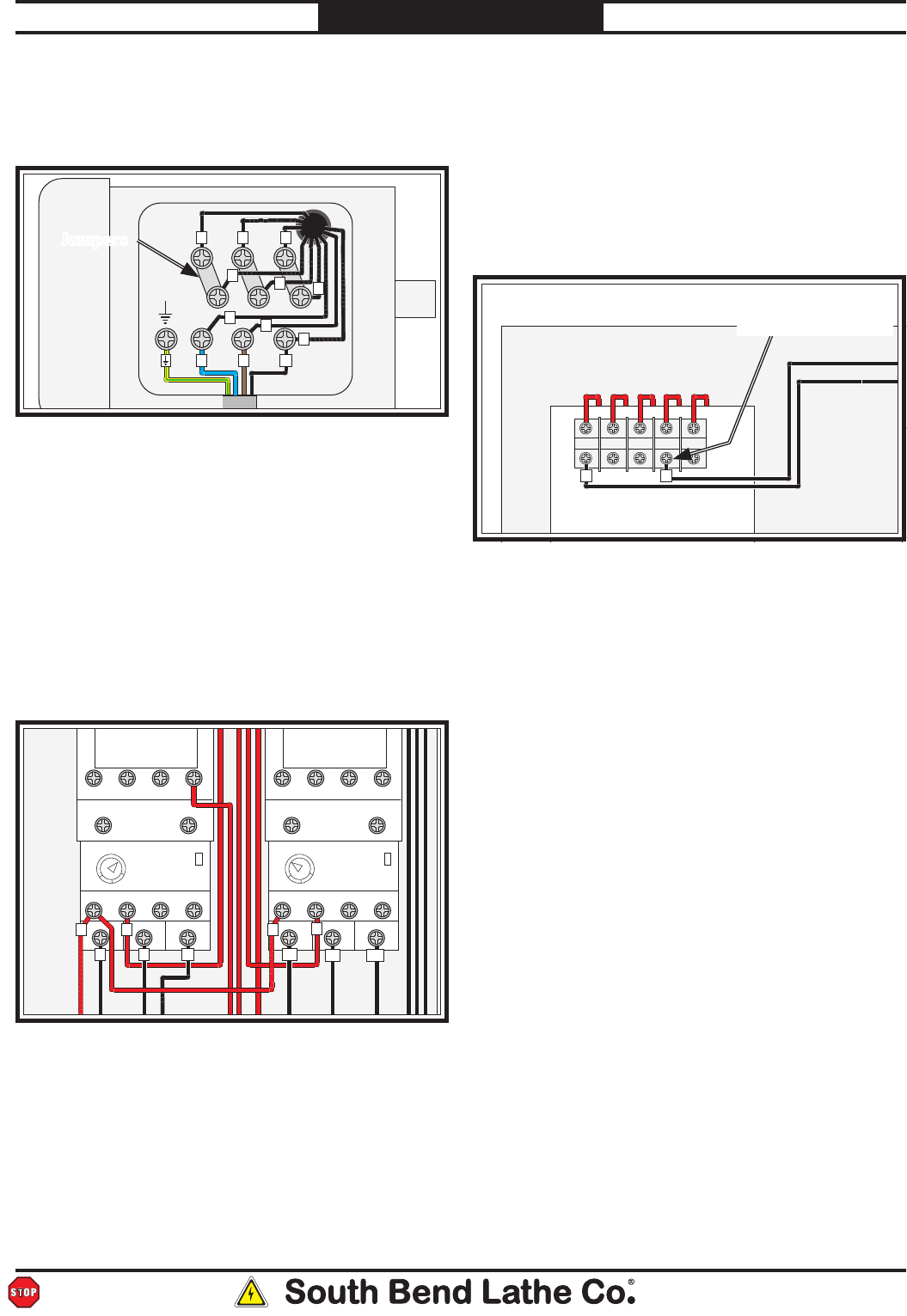
wires, reposition the jumpers as shown in
Figure 54. Stack the jumpers as needed,
since there will be two extras.
Figure 54. 440V Jumper locations.
GND
U
1
2
3
4 5 6
V W
Motor
7
8
9
Jumpers
4. Tighten the nine screws that secure the
wires and jumpers, making sure the wires
are still located in their original positions.
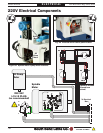
5. Open the electrical box on the side of the
machine. Loosen all of the screws that secure
the wires to the thermal relays and the
screws that secure the thermal relays to the
contactors (Figure 55). Pay careful attention
to the location of the wires so you can replace
them in the same position later.
Figure 55. 220V Thermal relays.
AMP
THERMAL
RELAY
CONTACTOR
Allen Bradley
C09400
1357L1 L2 L3 L4
2468T1 T2 T3 T4
95 96 NONC 97 98
AMP
AB 193 TAB60
AB 193 TAB24
THERMAL
RELAY
CONTACTOR
Allen Bradley
C09400
1357L1 L2 L3 L4
2468T1 T2 T3 T4
95
4
5
6
1.6 2.4
96 NONC 97 98
8
9
OO
U V W
W1
V1
U1
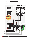
Figure 56. Wire "T" moved to 440V.
12345
R T
Transformer LCP-TBS
For 440V:
Set at 0.25A
For 440V:
"T" Positioned at 440V
012240110
0 208 220 440 480
Wire "T" moved to
440V Terminal
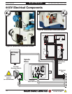
6. Replace the installed relays for the coolant
pump relay and spindle motor with the
relays from the 440V conversion kit,
installing all of the wires in the same
location from which they were removed.
7. Move the "T" wire from the 220V terminal
to the 440V terminal on the transformer, as
shown in Figure 56.
8. Hardwire the machine to a 440V locking
disconnect switch.
READ ELECTRICAL SAFETY
ON PAGE 39 FIRST!