For Machines Mfg. Since 8/09 Model SB1029
-21-
OPERATION
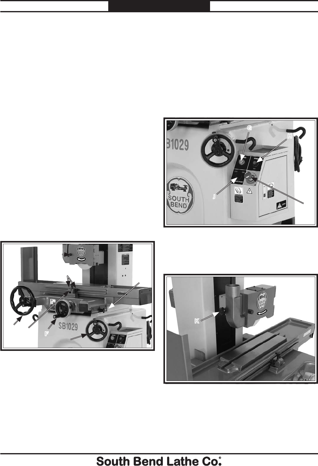
Controls
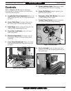
Refer to Figures 16–18 and the following
descriptions to become familiar with the basic
controls of this machine.
A. L
ongitudinal Travel Handwheel: Moves the
table back and forth on the longitudinal axis
(X-Axis).
B. Cente
r Table Stop: Provides a barrier for
the table stops to limit table movement.
C. Tab
le Stops: Adjust along the length of the
table to limit longitudinal travel.
D Cr
oss Axis Lock Knob: Locks the cross
table movement.
E El
evation Handwheel: Controls vertical
movement (Z-Axis) of the grinding wheel
assembly.
F. Cro
ss Travel Handwheel: Moves the table
forward and backward along the cross axis
(Y-Axis).
G. P
ower Indicator Light: Illuminates when
the grinding wheel motor is running.
H. Po
wer On Button: Supplies power to the
grinding wheel motor.
I. Em
ergency Stop (Off) Button: Cuts power
to the grinding wheel motor.
J. Co
olant Pump Switch: Control switch for
the optional coolant pump accessory.
K. P
ort Lock Knob: Locks the dust port into
position so it can be vertically positioned in
the spark path.
Figure 16. Basic controls.
A
B
C
D
E
F
Figure 18. Port lock knob.
Figure 17. Control panel.
H
I
J
K
G


