


6
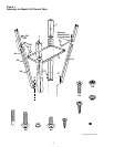
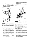
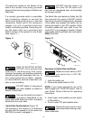
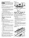
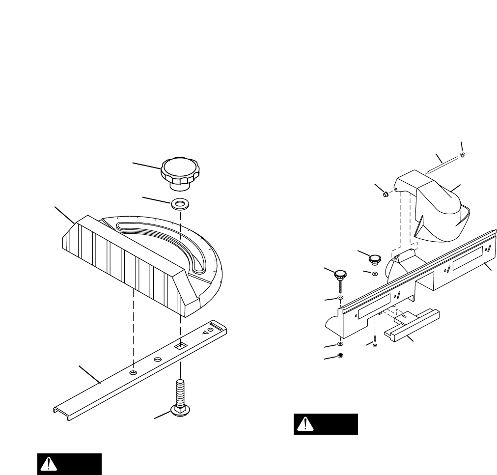
Assemble Plastic Miter Guide
(See Figure 3.)
1. Assemble miter gauge by threading car-
riage bolt (BB) through miter bar (S).
2. Place washer (II) and knob (N) on end of
carriage bolt. Tighten knob.
Figure 3
Vibrations from normal routing
may loosen the washer and bolt
that hold the rod to the plate. Occasionally
check these components to make sure they
are tight.
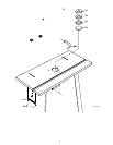
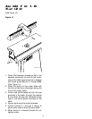
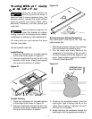
Assemble Jointing Fence to Router Table
Fence
1. Using the slots on the fence as guides,
slide the jointing fence (C) part way into
the router table fence (B).
2. Using the adjusting knob (N), washer (II),
and bolt (CC), assemble the jointing fence
to the router table fence.
3. Slide the jointing fence into the router
table fence as far as you can. Tighten the
adjusting knob.
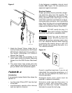
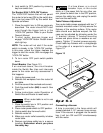
Attach Security Guard to Fence
1. Position the two holes on the security
guard so that they align with the two holes
on the fence. See Figure 4.
WARNING
GUIDE1
60
45
30
15
0
15
30
45
60
II
BB
S
N
E
2. Slide pivot pin (V) through holes in fence
and security guard. Secure by tapping on
two cap nuts (LL).
3. Test moveability by moving security guard
up and down.
Figure 4
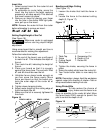
Mounting the Router
Always remove router bits and
unplug router before mounting
to router table.
The table will accept routers with bases up to
7" in diameter. There are two methods for
attaching routers to router table:
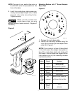
Mounting Routers With Three Hole Base
Plate Hole Configuration Pattern “E.” (See
Figures 5 and 7 with chart.)
1. Remove router base plate from router by
removing three screws.
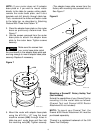
2. Loosen knobs and slide fences so that
notches in fences line up to clear mount-
ing holes.
3. While holding router upside down, posi-
tion it to the underside within the center
ring of the table top.
4. Rotate router until the three mounting
holes in router base line up with the three
larger holes in the table top.
CAUTION
WOLF113-34
C
CC
B
LL
K
LL
L
L
K
J
N
II
F