7
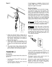
NOTE: For ease of use, position the router so
the ON-OFF switch is accessible from the
front of the table.
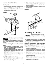
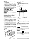
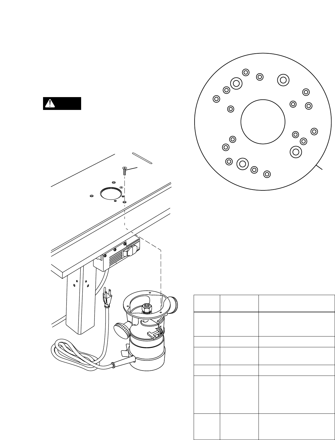
5. Insert three router base plate screws pre-
viously removed (T) through holes in table
top and into router mounting holes.
Tighten securely.
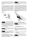
Make sure the screws from
router base plate are long
enough to mount router securely. Replace if
necessary.
Figure 5
PULL ON
PUSH OFF
RESET
O
U
T
L
E
T
S
WOLF113-8
F
CAUTION
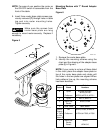
Mounting Routers with 7" Round Adaptor
Base Plate
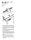
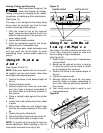
Figure 6
1. Remove the router base plate.
2. Identify the mounting scheme using the
chart and the drawing of the adaptor base
plate (I) in Figure 6.
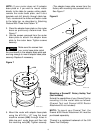
NOTE: If your router is not one of those listed
in the chart, place the adaptor base plate on
top of the router base plate and rotate until
the holes in the two plates are aligned. When
hole patterns line up, the mounting scheme
has been identified.
Hole Router Model
Pattern Brand Numbers
A Ryobi #R160K, #R160V,
#R165, #R180
Craftsman #27500, #27510, #27511
B Ryobi #R175, #RE175
C Black and #7600, #7604
Decker
D Porter Cable #690, #6931
Mount Skil #1823, #1835, #1845-02
Directly
to Table Craftsman #17504, #17505, #17506
or Use
Pattern E
F Black and #7612
Decker
Dewalt #DW 610
A
A
C
C
C
C
D
D
I
D
E
E
E
F
F
F
H
H
H
AB
AB
WOLF113-3


