


Measurement Operations & Settings Triggering - The TRIGger Subsystem
180 Agilent 8163A/B, 8164A/B & 8166A/B Mainframes, Fifth Edition
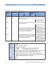
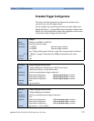
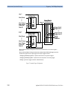
Figure 7 Extended Trigger Configuration
Node A Input
Slot 0 Event
Slot 17 Event
:trig 1
Input Trigger
Connector
Node B
Trigger Slot 0
Trigger Slot 1
Trigger Slot 16
Trigger Slot 17
Output
Trigger
Node A
Node B
Configuration
AND / OR
Node B Input
Slot 0 Event
Slot 17 Event
:trig 2
Input Trigger
Connector
Node A
Configuration
AND / OR
Output Matrix
0
0
0
0
0
Configuration
Connector
0
0
0
0
0
0
0
0
Bits set in Node A/B Input Configuration determine the conditions that can cause a trigger at
Bits set in Output Matrix Configuration determine whether Node A OR Node B triggers particular
Node A/B.
module slots or generates an output trigger at the Output Trigger Connector.
“:TRIGger[
n][:CHANnel[m]]:OUTPut” explains how slot events can generate triggers.
“:TRIGger[
n][:CHANnel[m]]:INPut” explains how a slot responds to an incoming trigger.
0
0
“:TRIGger” generates a trigger at Node A or Node B directly.
..... .....
....