


Measurement Operations & Settings Triggering - The TRIGger Subsystem
182 Agilent 8163A/B, 8164A/B & 8166A/B Mainframes, Fifth Edition
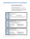
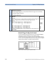
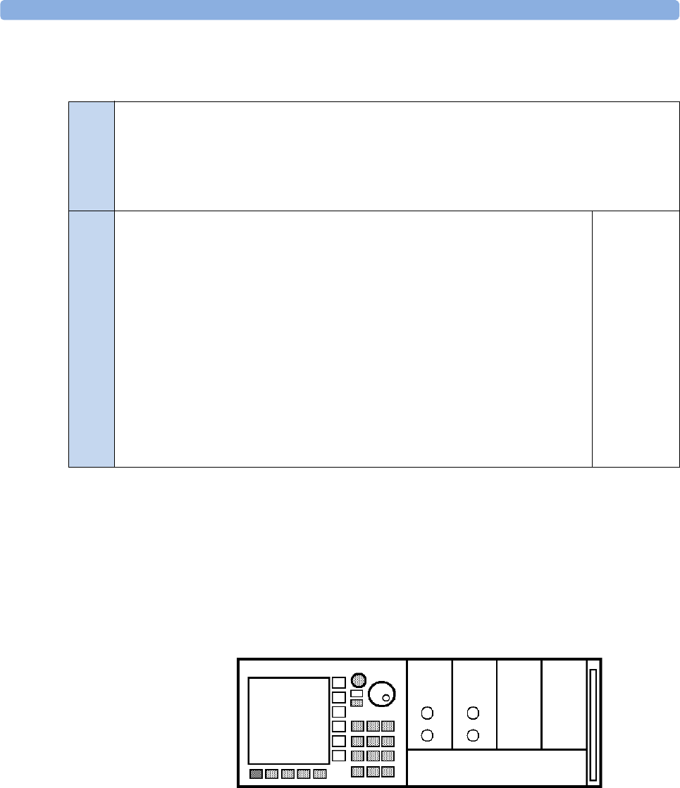
Extended Trigger Configuration Example
The short example below demonstrates how to use extended triggering
configuration to make tunable laser source modules sweep
simultaneously. Setup your mainframe with two Agilent 81689A modules
in slots 1 and 2. The example below presumes you set up identical stepped
sweeps for both modules, for example, by pressing PRESET.
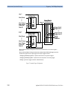
Figure 8 Setup for Extended Trigger Configuration Example
Output Matrix Configuration
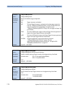
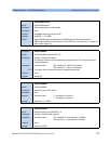
This 32-bit unsigned integer lets you choose Node A OR Node B to trigger each of the following:
• the Output Trigger Connector or
• individual module slots.
Bit
31
30
18-29
17
16
2
1
0
Mnemonic
Not used
Output Trigger Connector: 0 - a trigger at Node A is switched to the Output Trigger Con-
nector, 1 - a trigger at Node B is switched to theOutput Trigger Connector
Not used
Slot 17: 0 - Node A triggers slot 17, 1 - Node B triggers slot 17
Slot 16: 0 - Node A triggers slot 16, 1 - Node B triggers slot 16
Slot 2: 0 - Node A triggers slot 2, 1 - Node B triggers slot 2
Slot 1: 0 - Node A triggers slot 1, 1 - Node B triggers slot 1
Slot 0: 0 - Node A triggers slot 0, 1 - Node B triggers slot 0
“:TRIGger[n][:CHANnel[m]]:INPut” on page 173 explains how a slot responds to an in-
coming trigger.
Hexadecimal
0
#H40000000
0
#H20000
#H10000
#H4
#H2
#H1
....
....
Tunable
Laser
Tunable
Laser