


1-5
Cisco 800 Series Routers Hardware Installation Guide
78-5373-04
Chapter 1 Overview
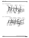
Back Panels
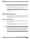
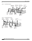
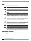
Figure 1-5 Cisco 802 Router Back Panel
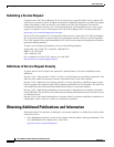
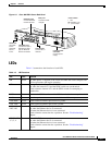
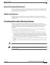
Figure 1-6 Cisco 803 Router Back Panel
11667
ISDN U
CONSOLE
ETHERNET
Cable lock
Use cable
lock to
physically
secure
router.
Link LED
Indicates state
of Ethernet port.
HUB/NO HUB button
(for Ethernet port)
Determines cable
type for Ethernet
device connection.
Ethernet port
Connect Ethernet
network device.
Console port
Connect PC
or terminal.
ISDN BRI U port
Connect to
ISDN wall jack.
Locking power
connector
Connect power
supply.
Power switch
l = On.
= Standby or no power output.
Cisco 802
LINK
HUB
NO HUB
10 BASE T
11668
ISDN S/T
1
2
CONSOLE
ETHERNET 10 BASE T
1
2
3
Cable lock
Use cable
lock to
physically
secure
router.
Ethernet ports
Connect Ethernet
network devices.
Console port
Connect PC or
terminal.
ISDN BRI S/T port
Connect to external
NT1 or ISDN wall jack.
Telephone ports
Connect to telephone,
fax machine, or modem.
Locking power
connector
Connect power
supply.
HUB
NO HUB
Power switch
l = On.
= Standby or
no power output.
Cisco 803
PHONE
0
HUB/NO HUB button
(for Ethernet port 0)
Determines cable
type for Ethernet
device connection.