


2-20
Cisco 800 Series Routers Hardware Installation Guide
78-5373-04
Chapter 2 Installation
Verifying Installation
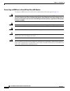
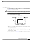
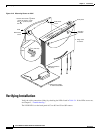
Figure 2-12 Mounting Router on Wall
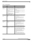
Verifying Installation
Verify the cable connections (links) by checking the LEDs listed in Table 2-4. If the LEDs are not on,
see Chapter 3, “Troubleshooting.”
The LINK LED is on the back panel of Cisco
801 and Cisco 802 routers.
7 in. (19.35 cm)
11672
Wall-mount
screw
Wall-mount
screw
Wall
Mounting
brackets
Front panel
1. Secure two screws 7 inches
(19.35 cm) apart in a wall
and in. (0.32 cm) from
the wall.
2. Hang router
on screws.
3. Place power supply
on horizontal surface.
Maximum distance
6 ft (18 m)
5
8
5
8
1
8
Screw
in. (0.32 cm)
1
8
Wall