


1-6
Cisco 800 Series Routers Hardware Installation Guide
78-5373-04
Chapter 1 Overview
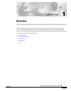
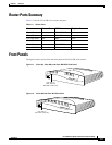
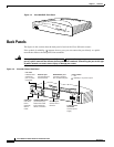
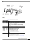
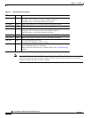
Back Panels
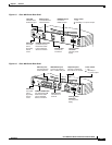
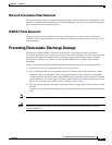
Figure 1-7 Cisco 804 Router Back Panel
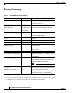
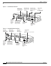
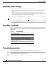
Figure 1-8 Cisco 802 IDSL Router Back Panel
11669
ISDN U
Cable lock
Use cable
lock to
physically
secure
router.
Ethernet ports
Connect Ethernet
network devices.
Console port
Connect PC or
terminal.
ISDN BRI U port
Connect to ISDN
wall jack.
Telephone ports
Connect to telephone,
fax machine, or
modem.
Locking power
connector
Connect power
supply.
1
2
3
HUB
NO HUB
1
2
CONSOLE
Power switch
l = On.
= Standby or no
power output.
Cisco 804
PHO
NE
ETHERNET 10 BASE T
0
HUB/NO HUB button
(for Ethernet port 0)
Determines cable
type for Ethernet
device connection.
30771
IDSL
CONSOLE
ETHERNET
Cable lock
Use cable
lock to
physically
secure
router.
Link LED
Indicates state
of Ethernet port.
TO HUB/TO PC
(for Ethernet port)
Determines cable
type for Ethernet
device connection.
Ethernet port
Connect Ethernet
network device.
Console port
Connect PC
or terminal.
IDSL port
Connect to
IDSL wall jack.
Locking power
connector
Connect power
supply.
Power switch
l = On.
= Standby or no power output.
Cisco 802 IDSL
LINK
TO HUB
TO PC
10 BASE T