


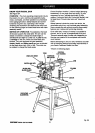
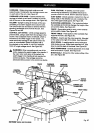
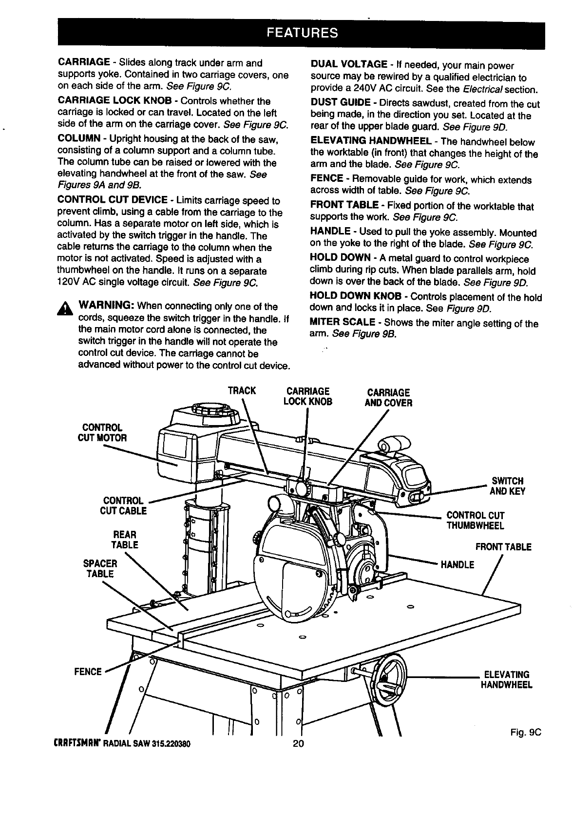
CARRIAGE- Slides along track under arm and
supports yoke. Contained in two carriage covers, one
on each side of the arm. See Figure 9C.
CARRIAGE LOCK KNOB - Controls whether the
carriage is locked or can travel. Located on the left
side of the arm on the cardage cover. See Figure 9C.
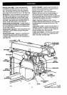
COLUMN - Upright housing at the back of the saw,
consisting of a column support and a column tube.
The column tube can be raised or lowered with the
elevating handwheel at the front of the saw. See
Figures 9A and 9B.
CONTROL CUT DEVICE - Limits carriage speed to
prevent climb, using a cable from the carriage to the
column. Has a separate motor on left side, which is
activated by the switch trigger in the handle. The
cable returns the carriage to the column when the
motor is not activated. Speed is adjusted with a
thumbwheel on the handle. It runs on a separate
t20V AC single voltage circuit. See Figure 9C.
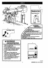
_k WARNING: When connecting only one of the
cords, squeeze the switch trigger inthe handle. If
the main motor cord atone is connected, the
switch trigger in the handle will not operate the
control cut device. The cardage cannot be
advanced without power to the control cutdevice.
DUAL VOLTAGE - If needed, your main power
source may be rewired by a qualified electrician to
provide a 240V AC circuit. See the E/ectrica/section.
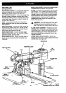
DUST GUIDE - Directs sawdust, created from the cut
being made, in the direction you set. Located at the
rear of the upper blade guard. See Figure 9D.
ELEVATING HANDWHEEL - The handwheel below
the worktable (in front) that changes the height of the
arm and the blade. See Figure 9C.
FENCE - Removable guide for work, which extends
across width of table. See Figure 9C.
FRONT TABLE - Fixed portion of the worktable that
supports the work. See Figure 9C.
HANDLE - Used to puUthe yoke assembly. Mounted
on the yoke tothe right of the blade. See Figure 9C.
HOLD DOWN - A metal guard to control workpiece
climb during rip cuts. When blade parallels arm, hold
down is over the back of the blade. See Figure 9D.
HOLD DOWN KNOB - Controls placement of the hold
down and locks it in place. See Figure 9D.
MITER SCALE - Shows the miter angle setting of the
arm. See Figure 9B.
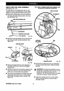
TRACK CARRIAGE CARRIAGE
LOCK KNOB ANDCOVER
CONTROL
CUTMOTOR
CONTROL
CUTCABLE
REAR
TABLE
SPACER
TABLE
SWITCH
ANDKEY
CONTROLCUT
THUMBWHEEL
FRONTTABLE
ELEVATING
HANDWHEEL
Fig. 9C
(RRFt'SNItN*RADIALSAW315.220380 20